CNC Joinery Jig

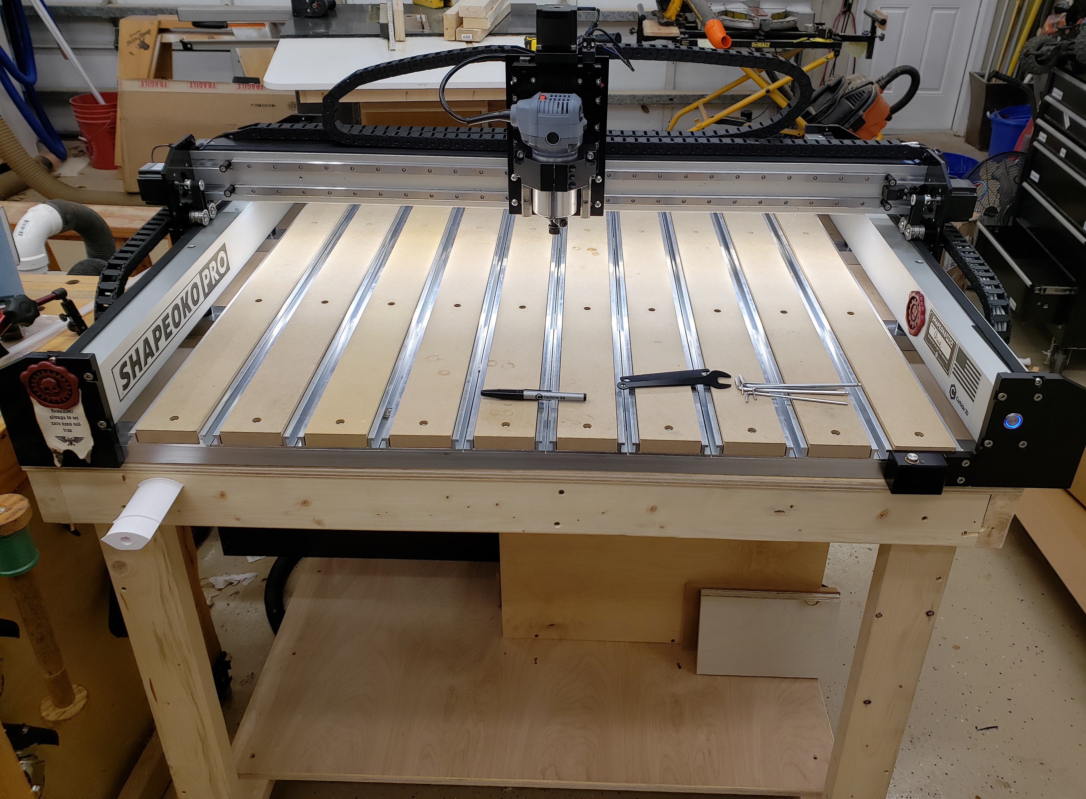
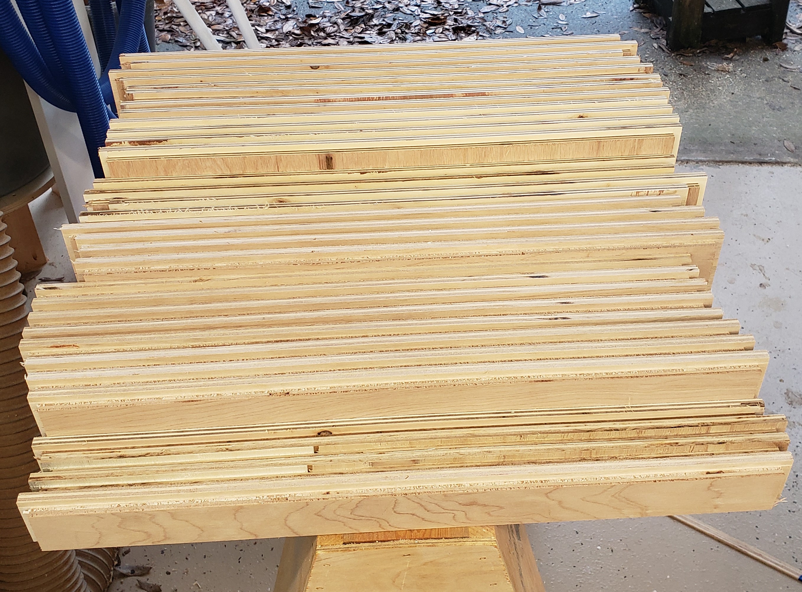
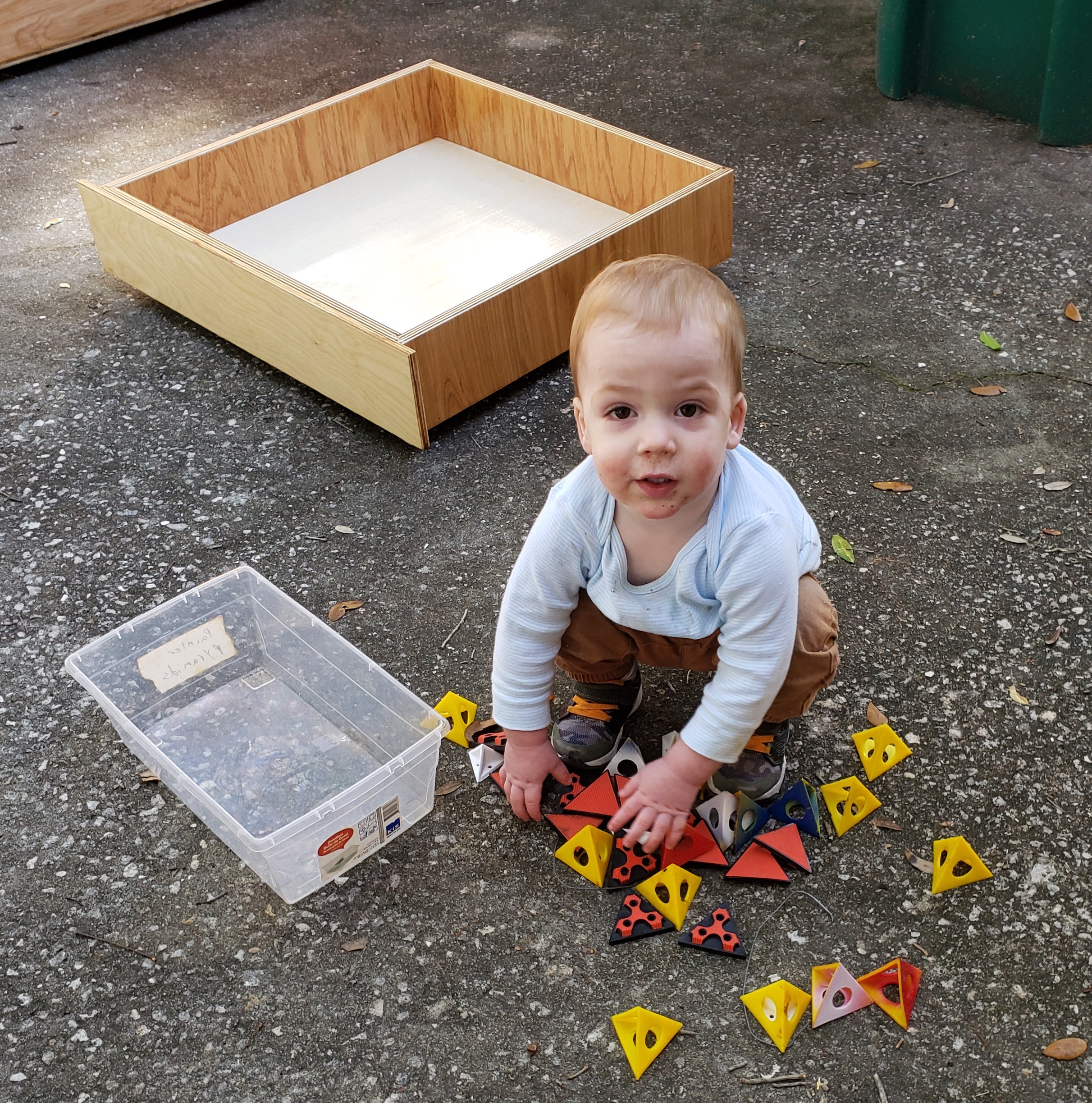
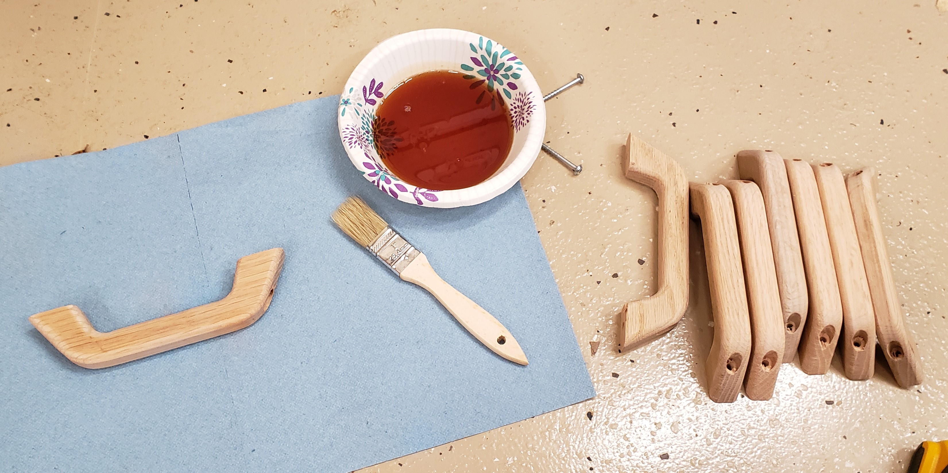
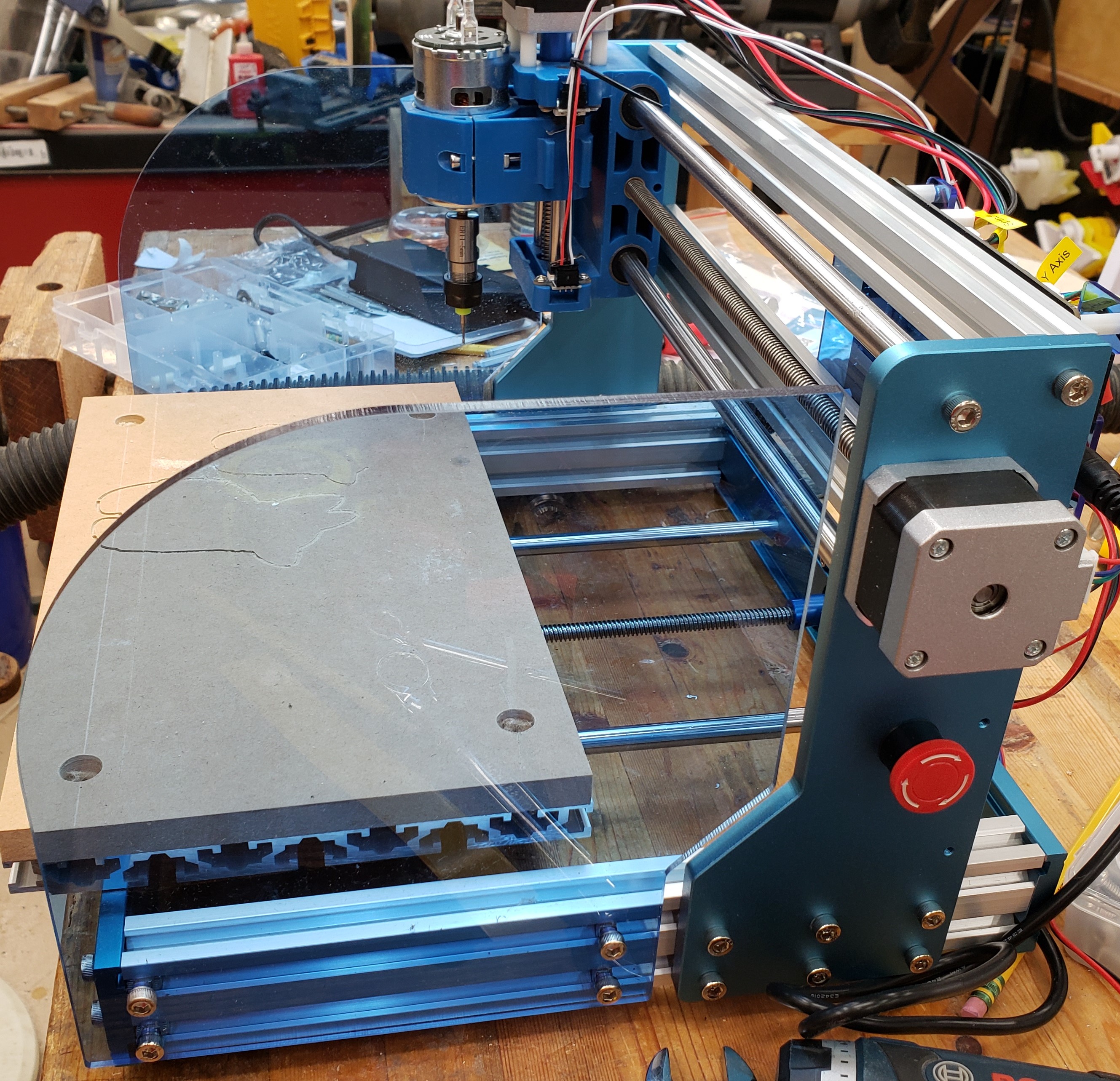
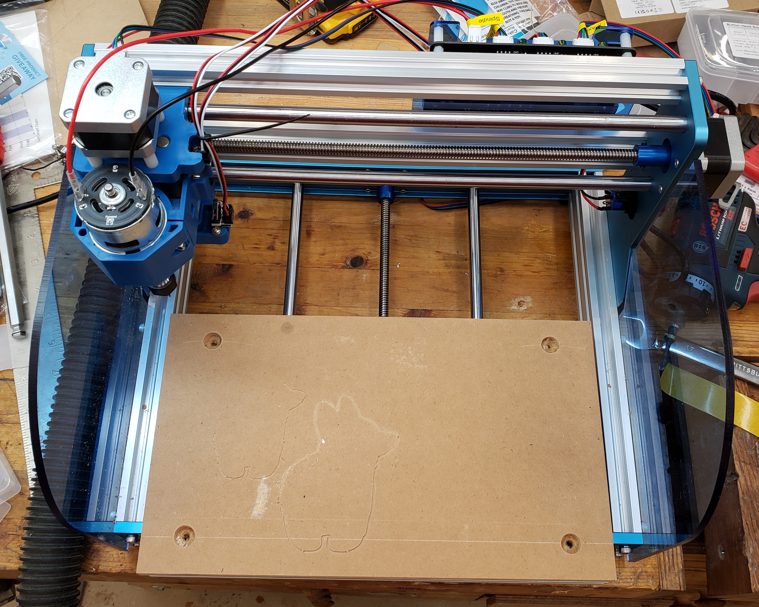
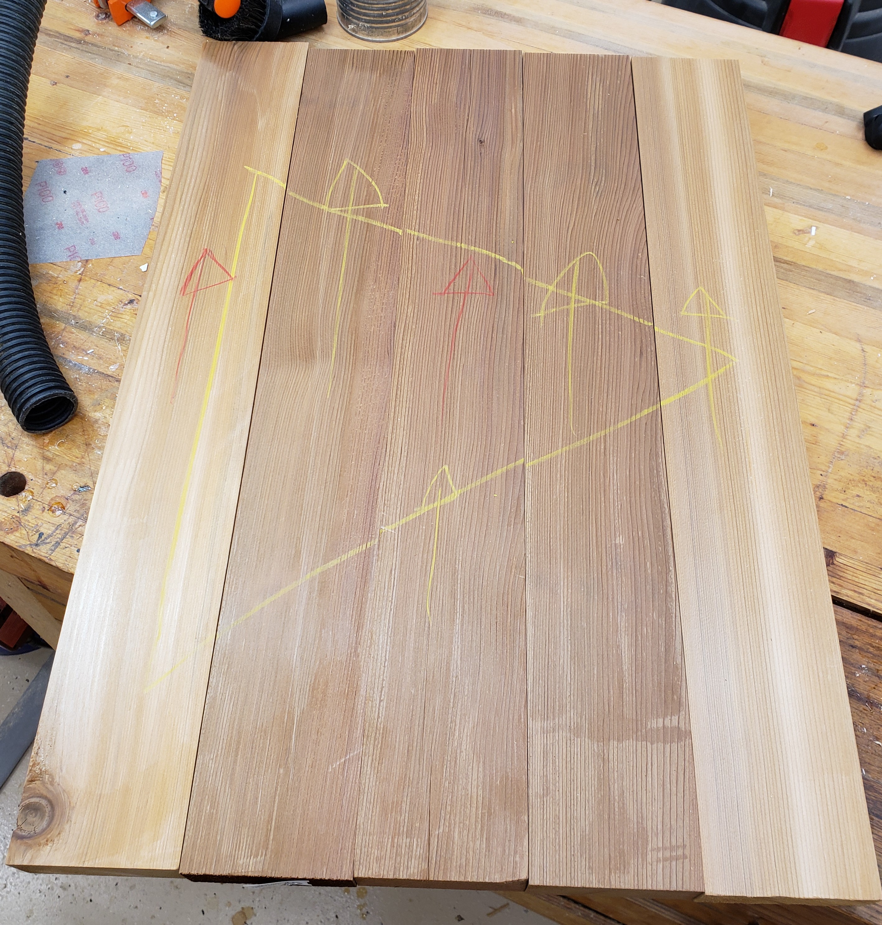
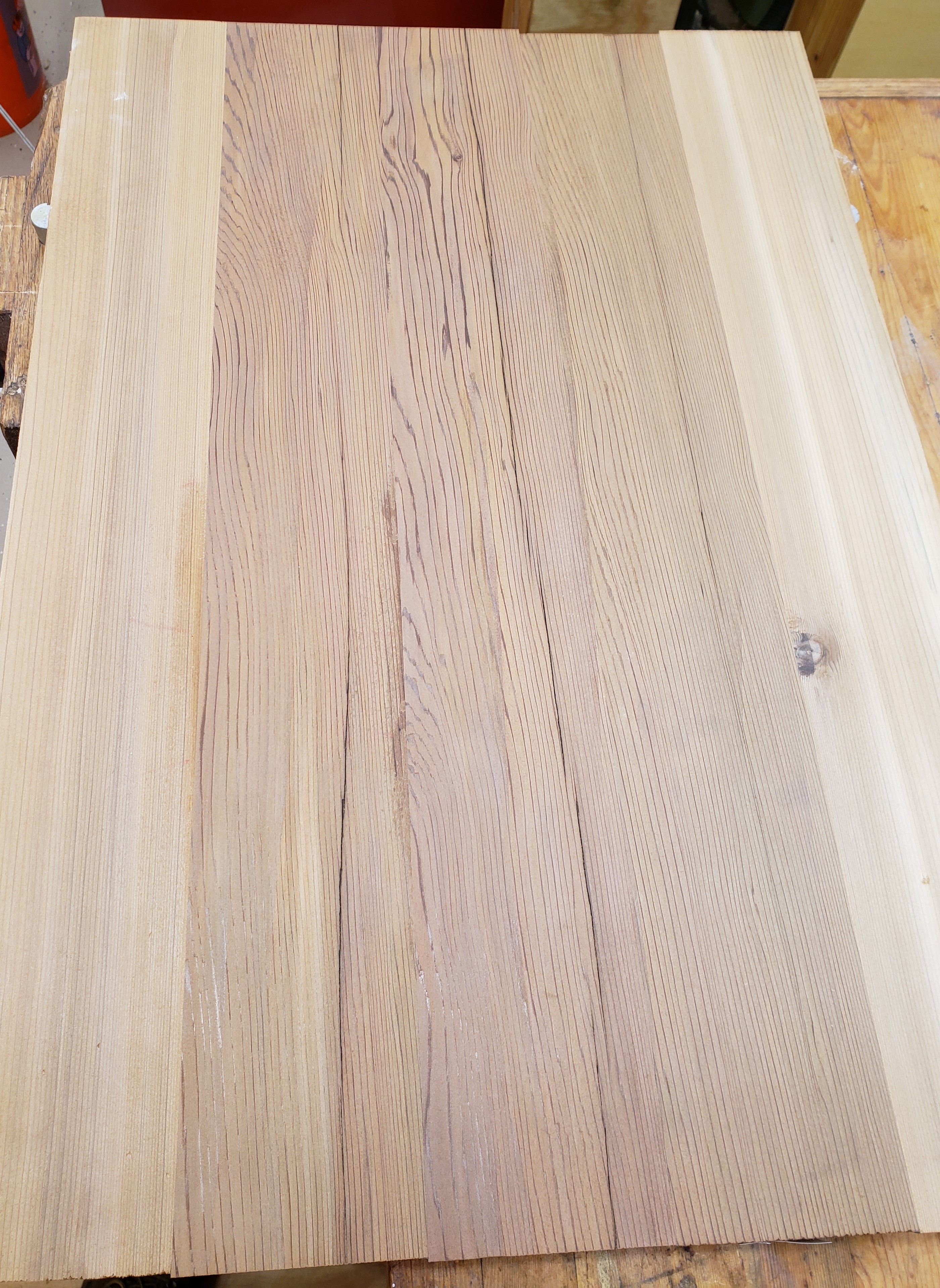
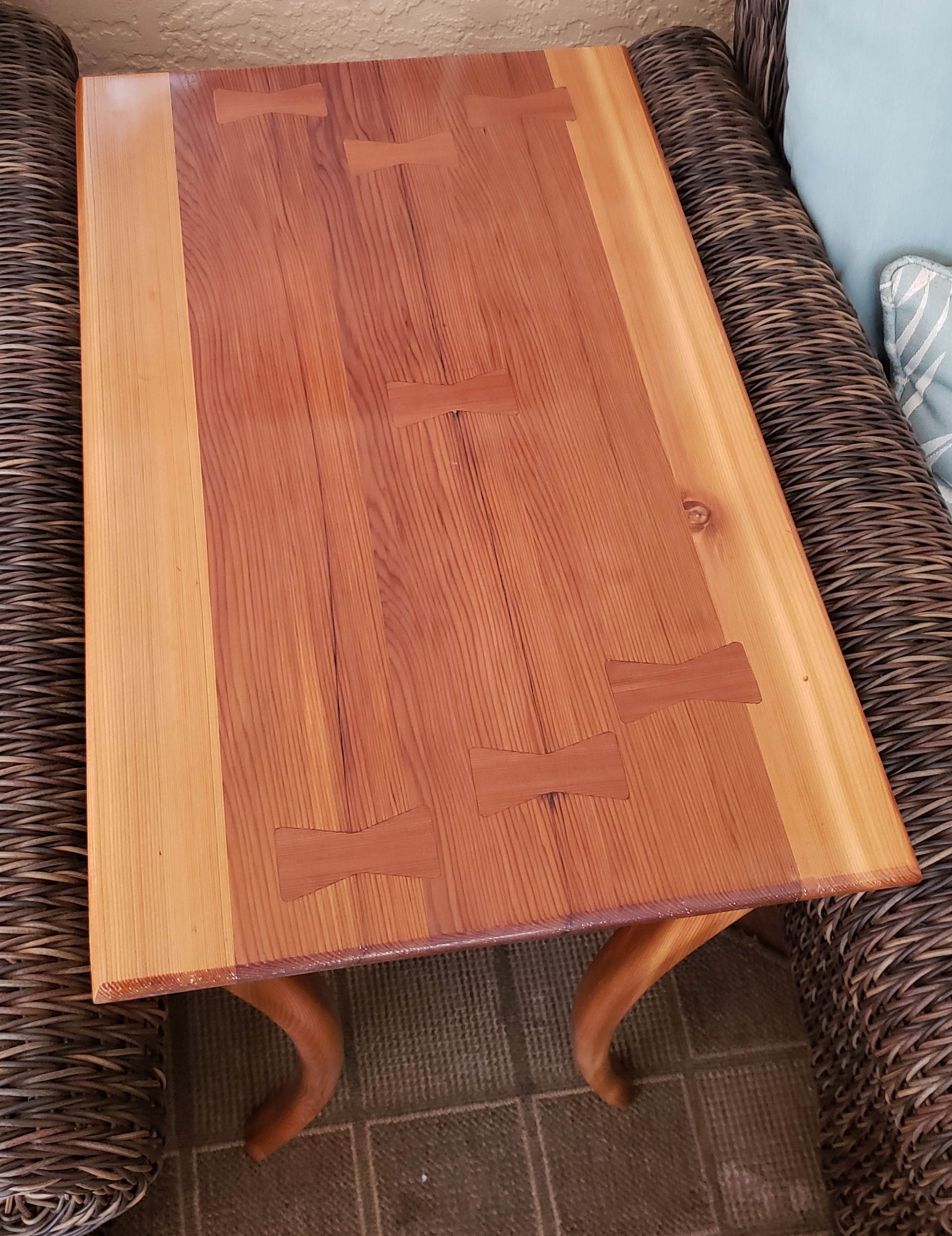
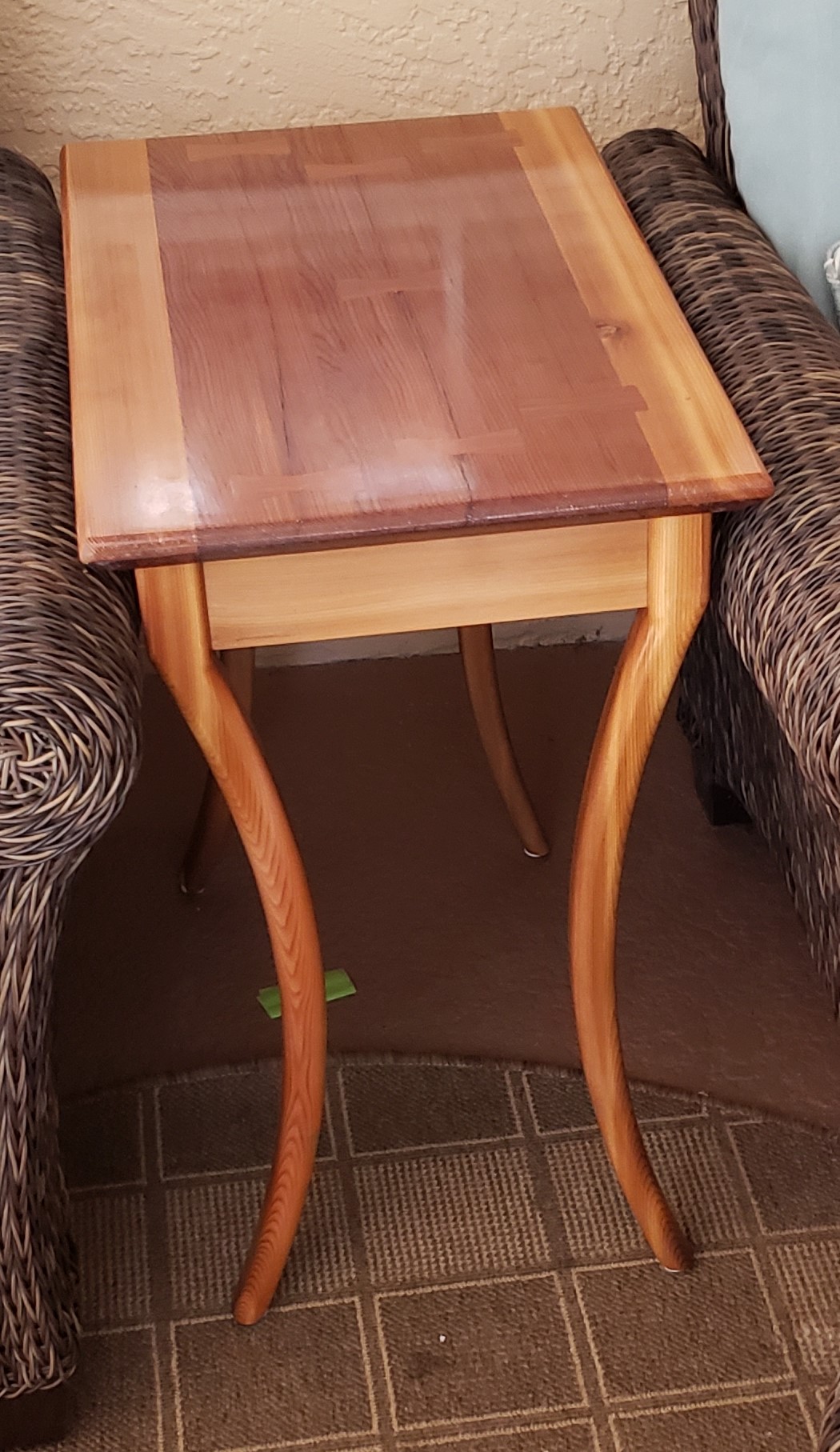
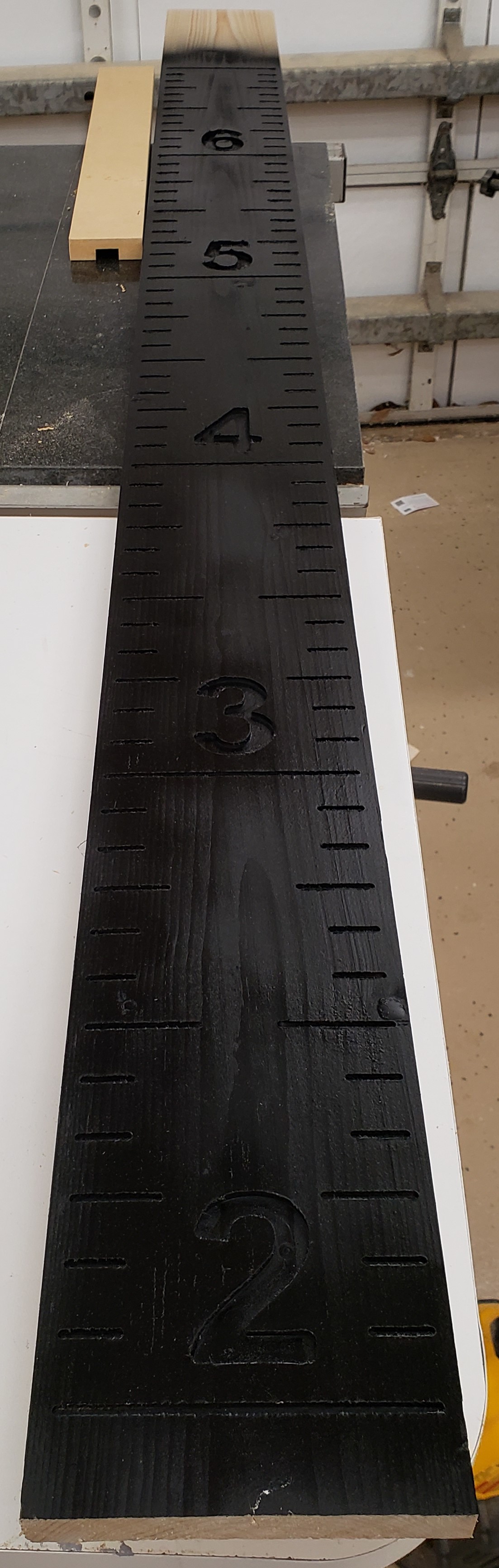
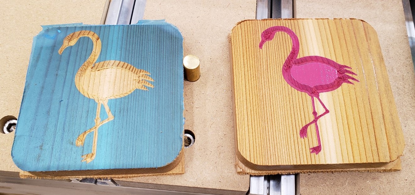
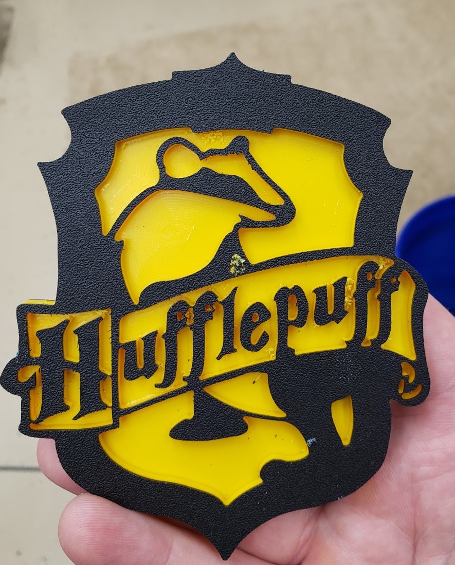
Updates have been few and far between recently. Being a toddler parent doesn’t afford me a lot of time in the shop, and the learning curve has been steep on the mill. That said, I have gotten a lot craftier with it and have fusion 360’s complicated CAM system pretty well whipped. I built a set of drawers for my mill and in the process created multiple versions of a joinery jig, and even dove into python code to post process my g-code. It will take a few posts to unravel it all. First up, a few shots of random fun coasters I made the past few months.
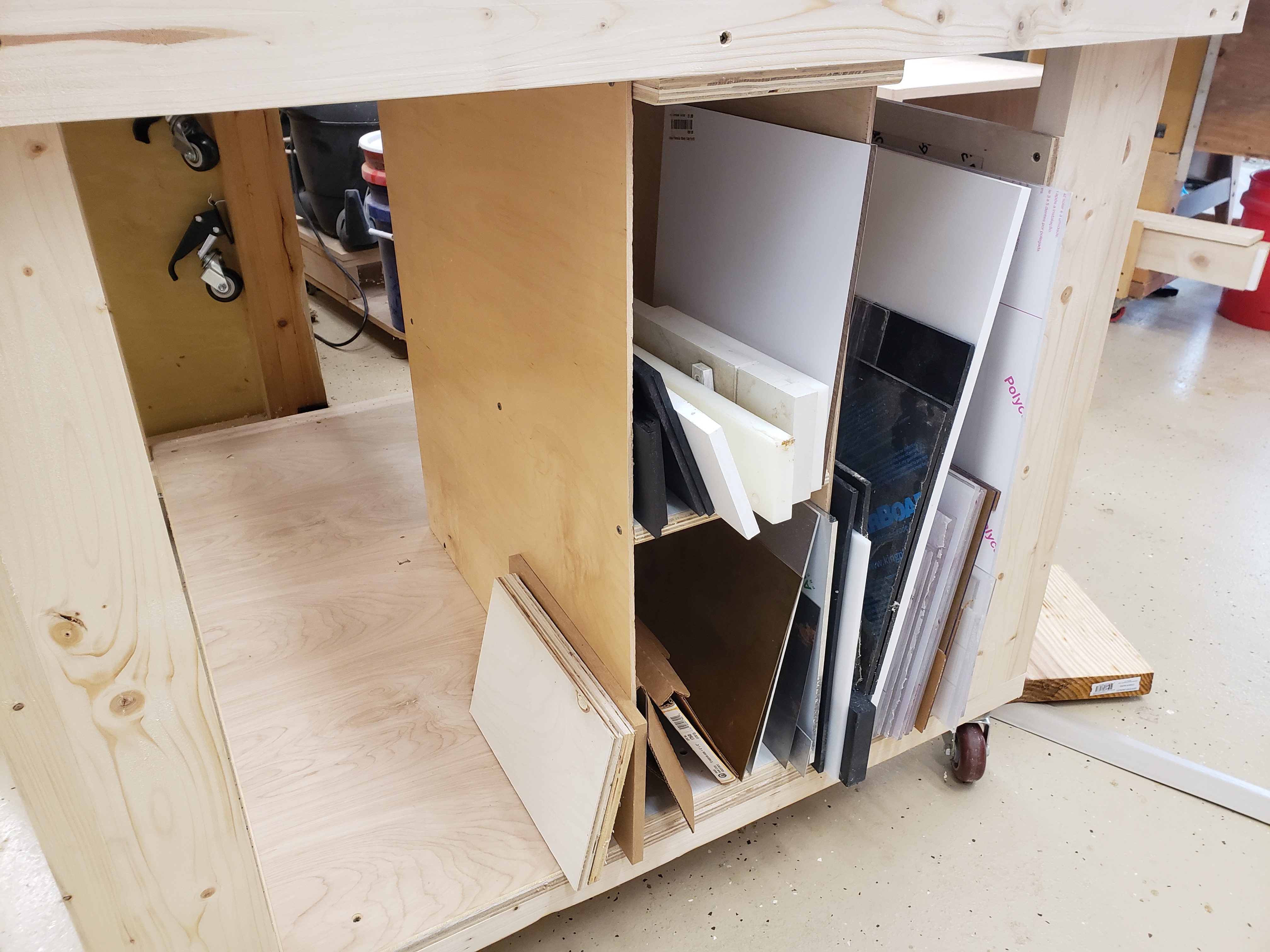
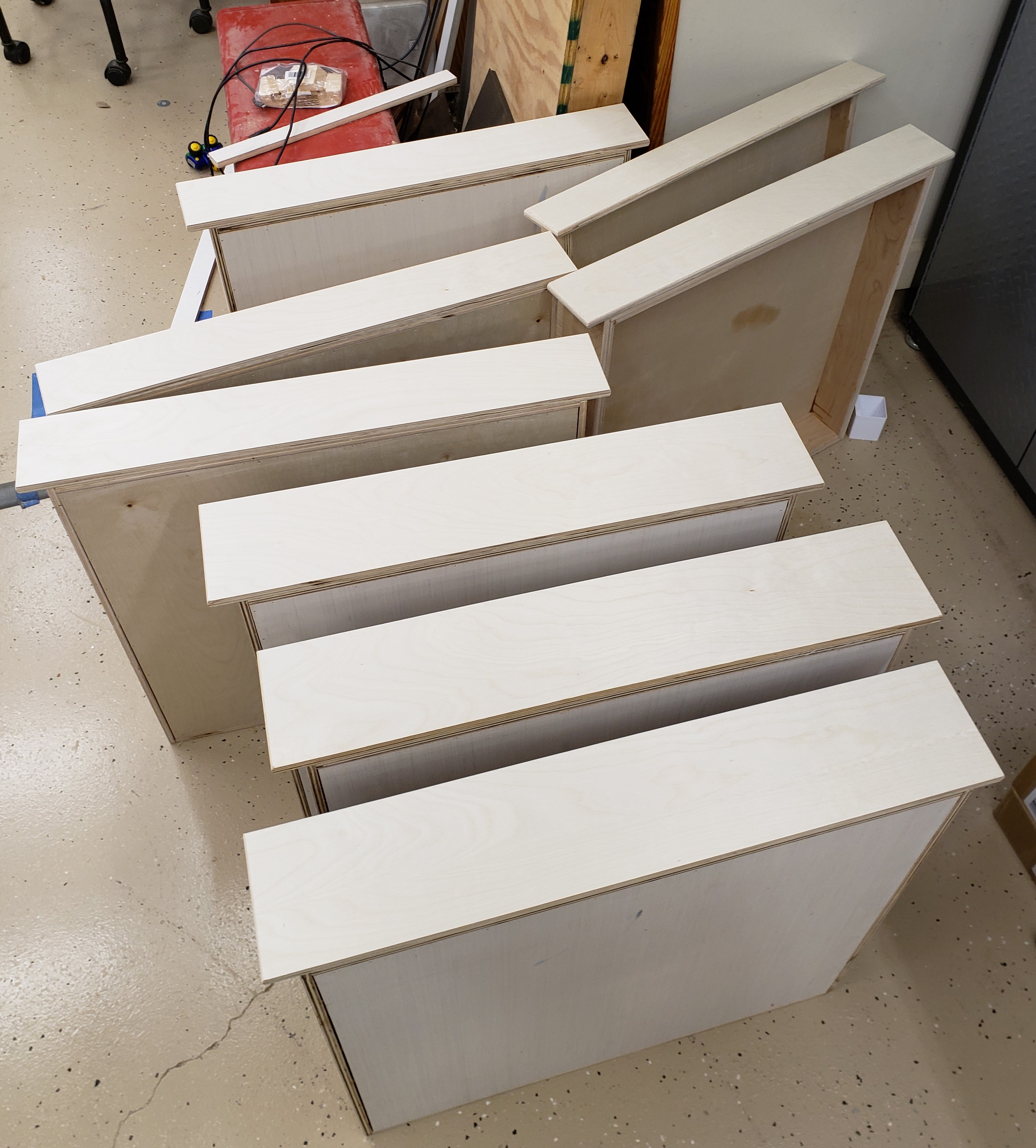
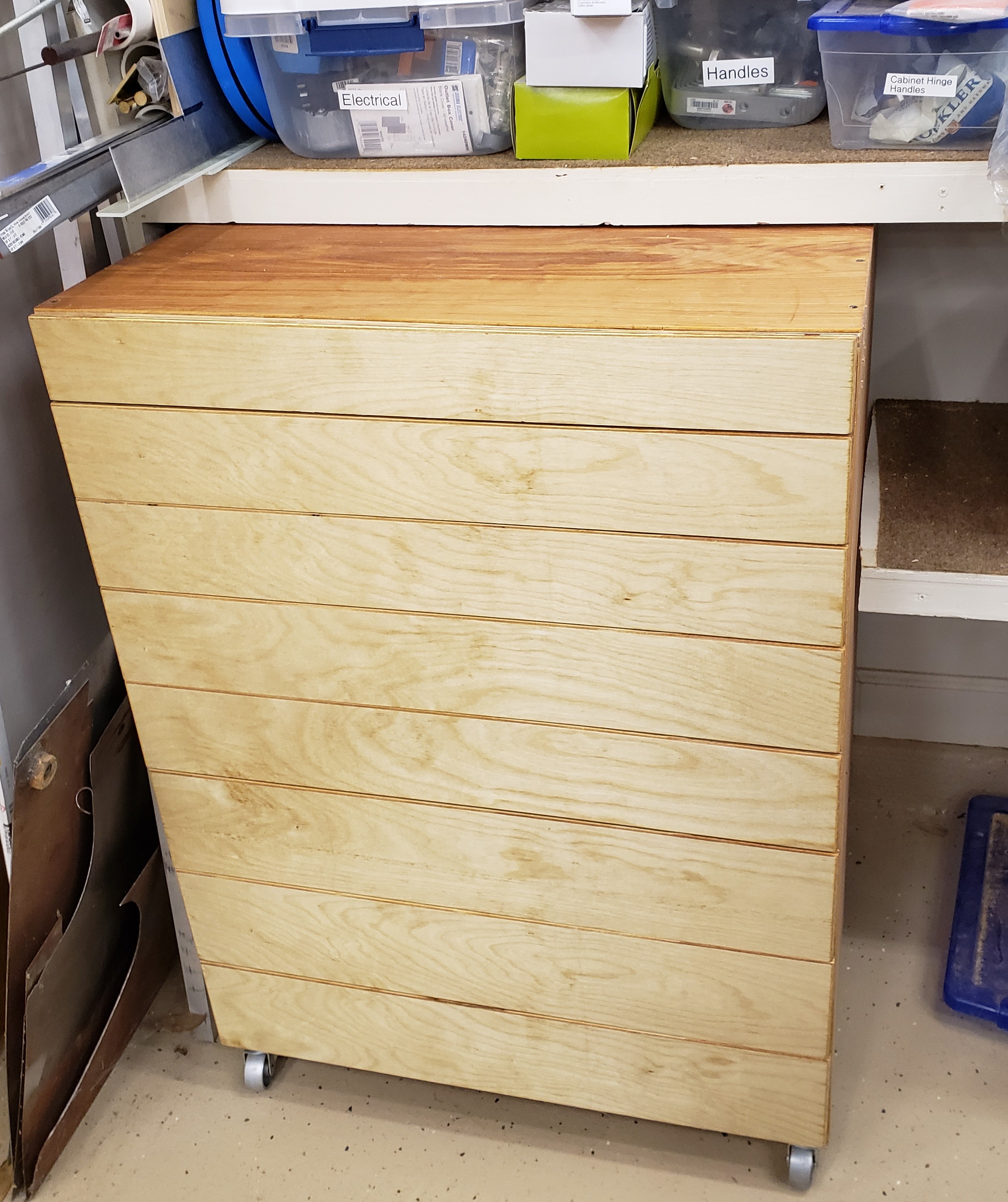
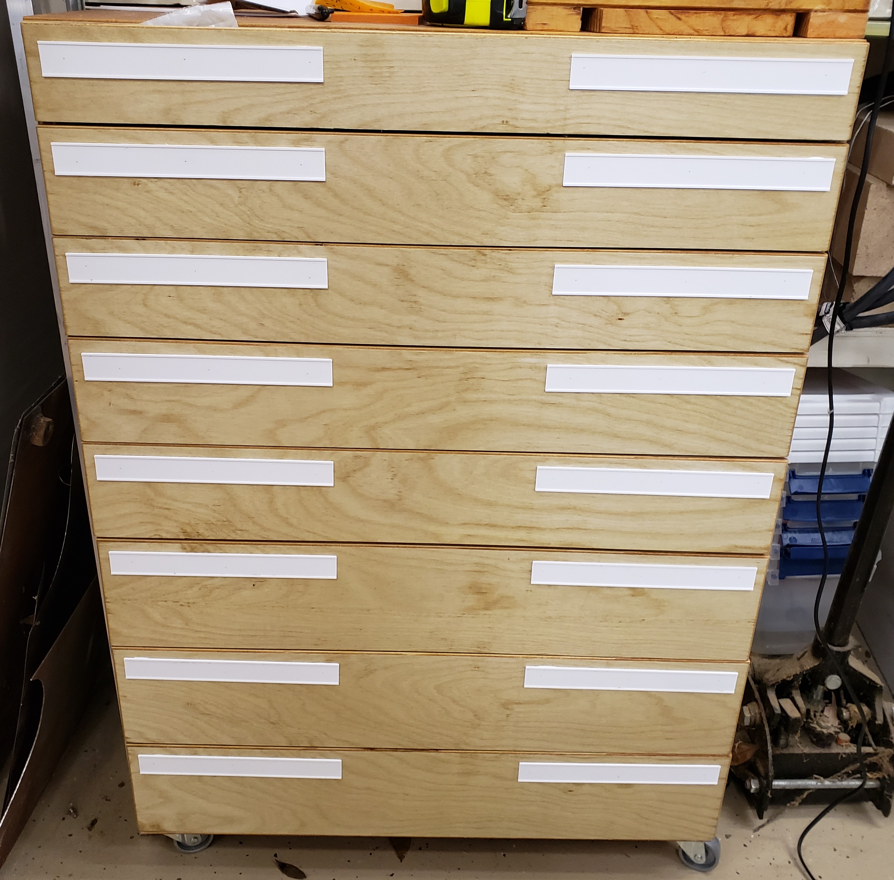
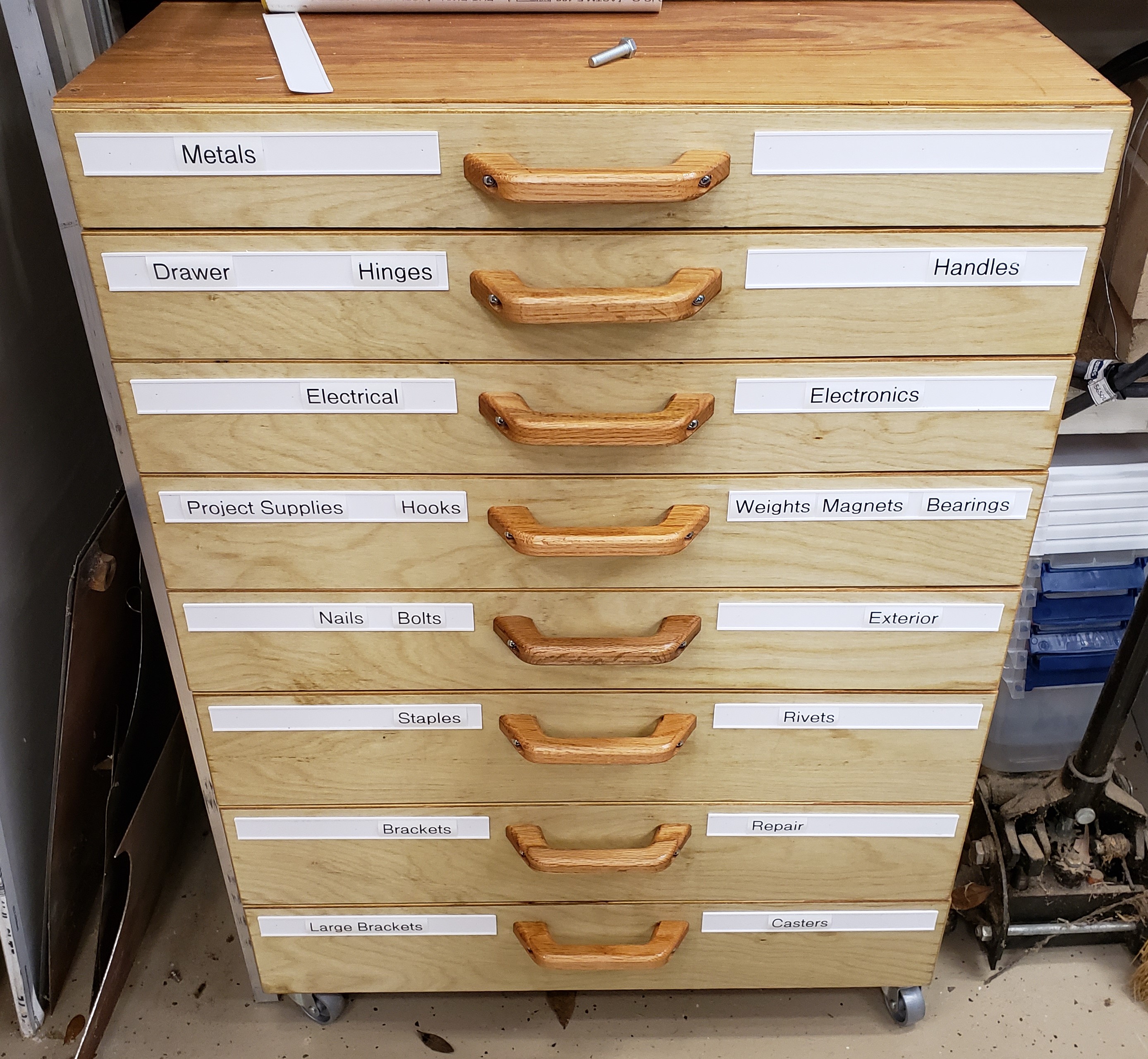
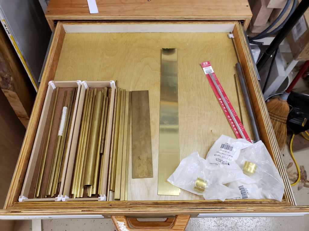
The Drawers

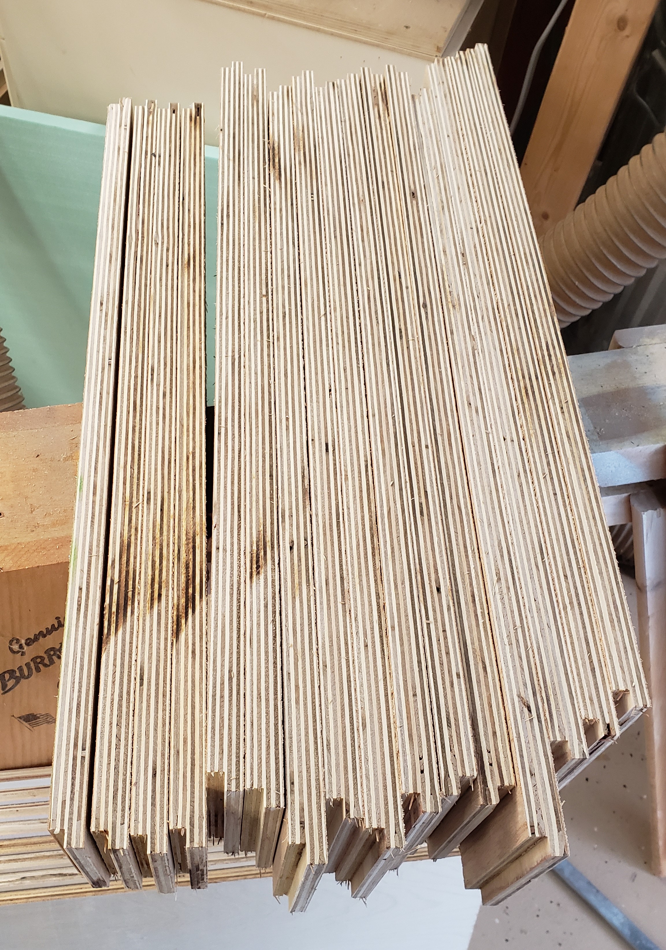
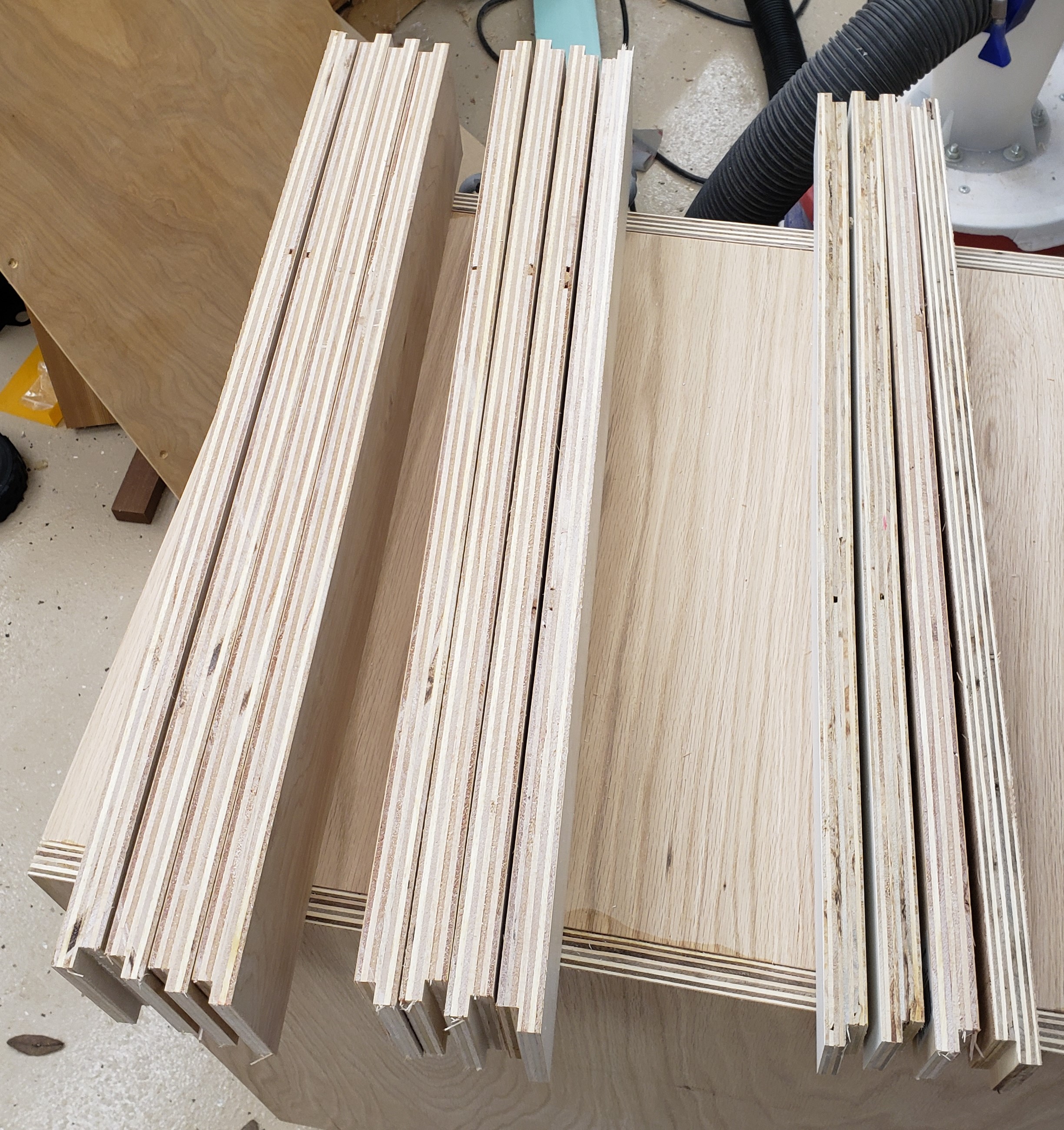
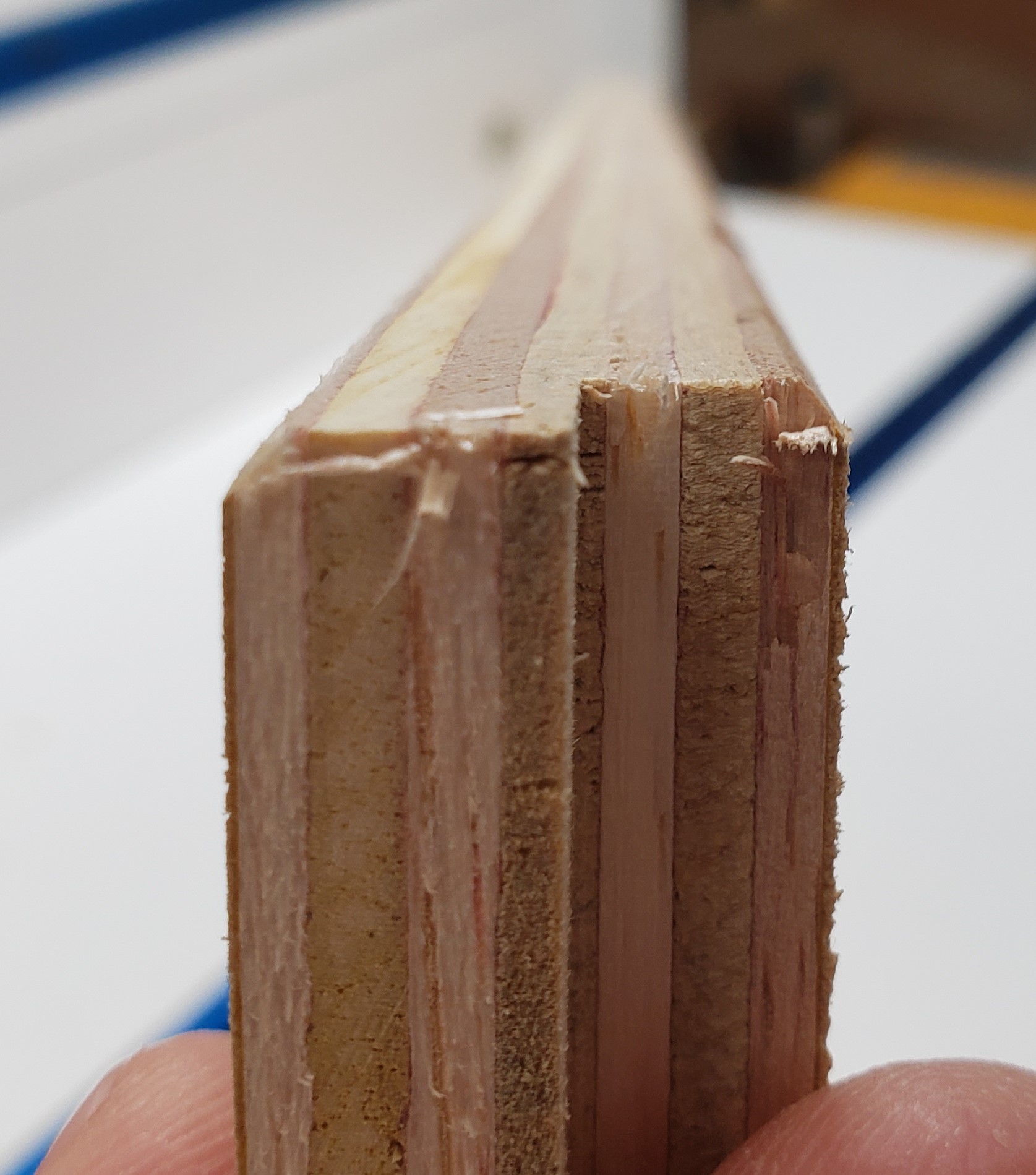
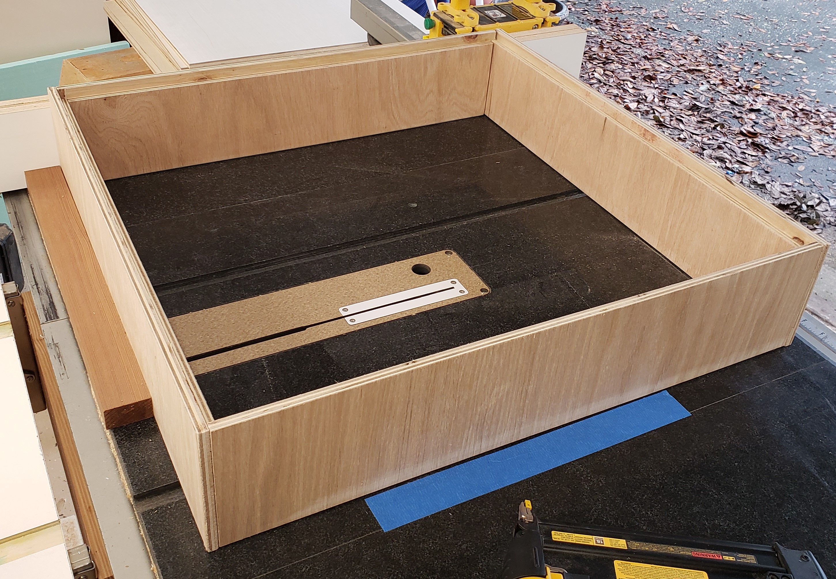
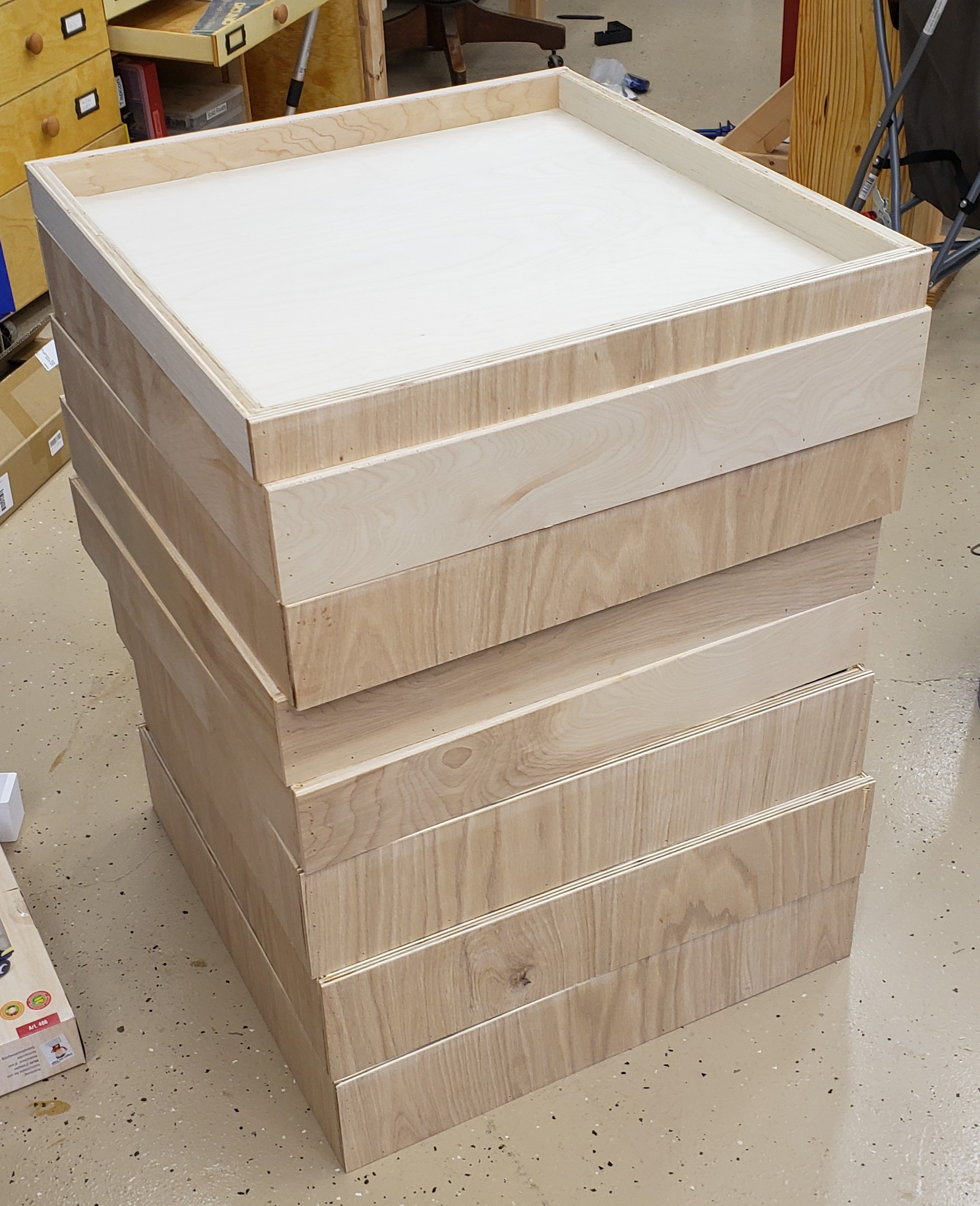
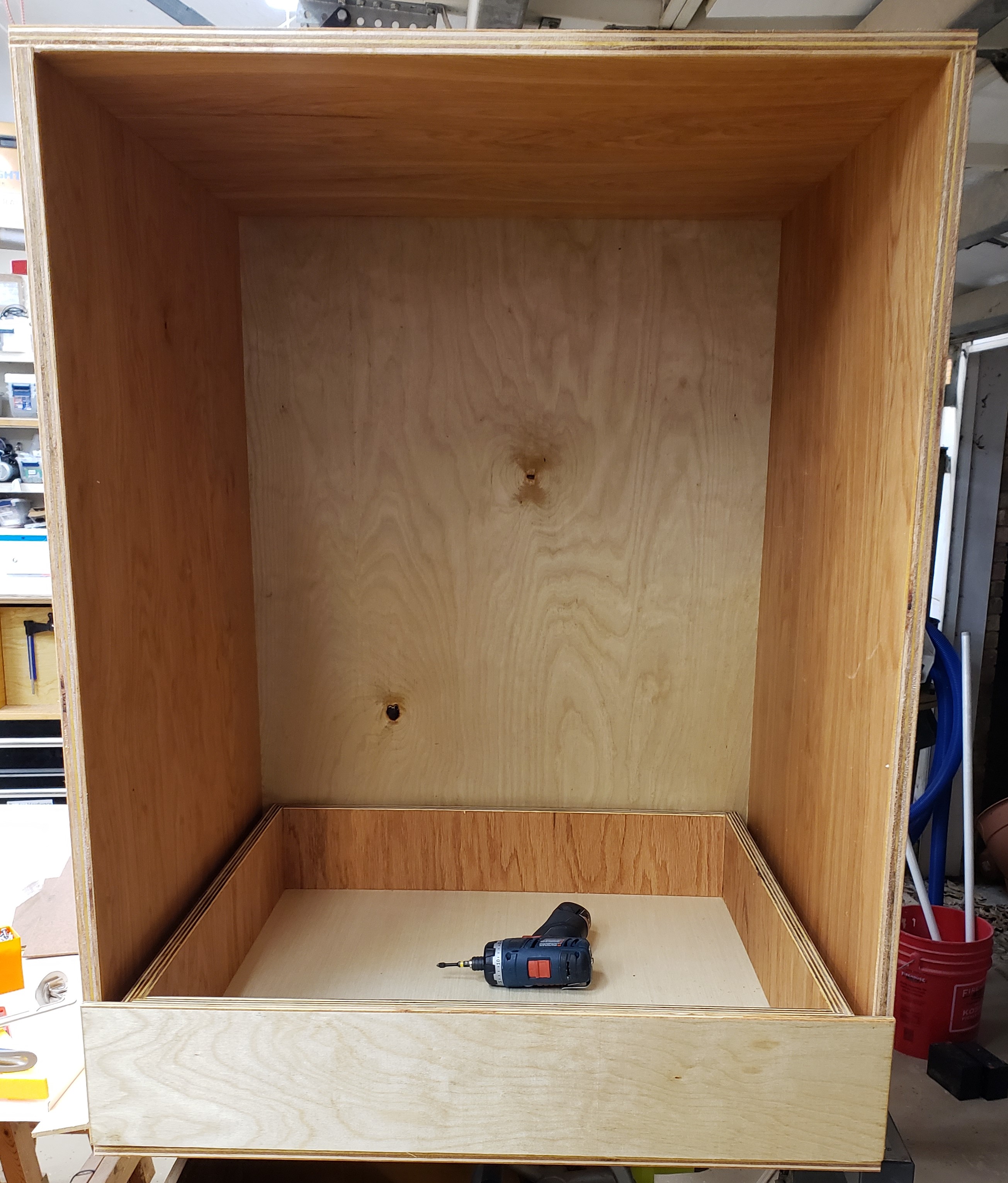
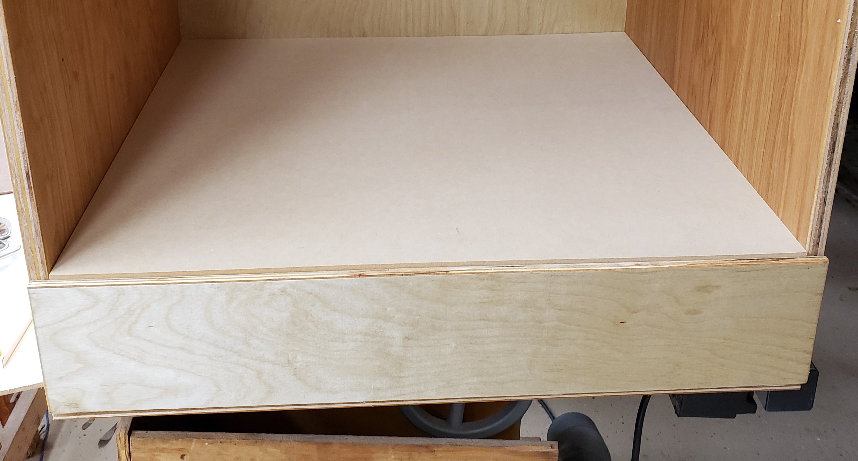
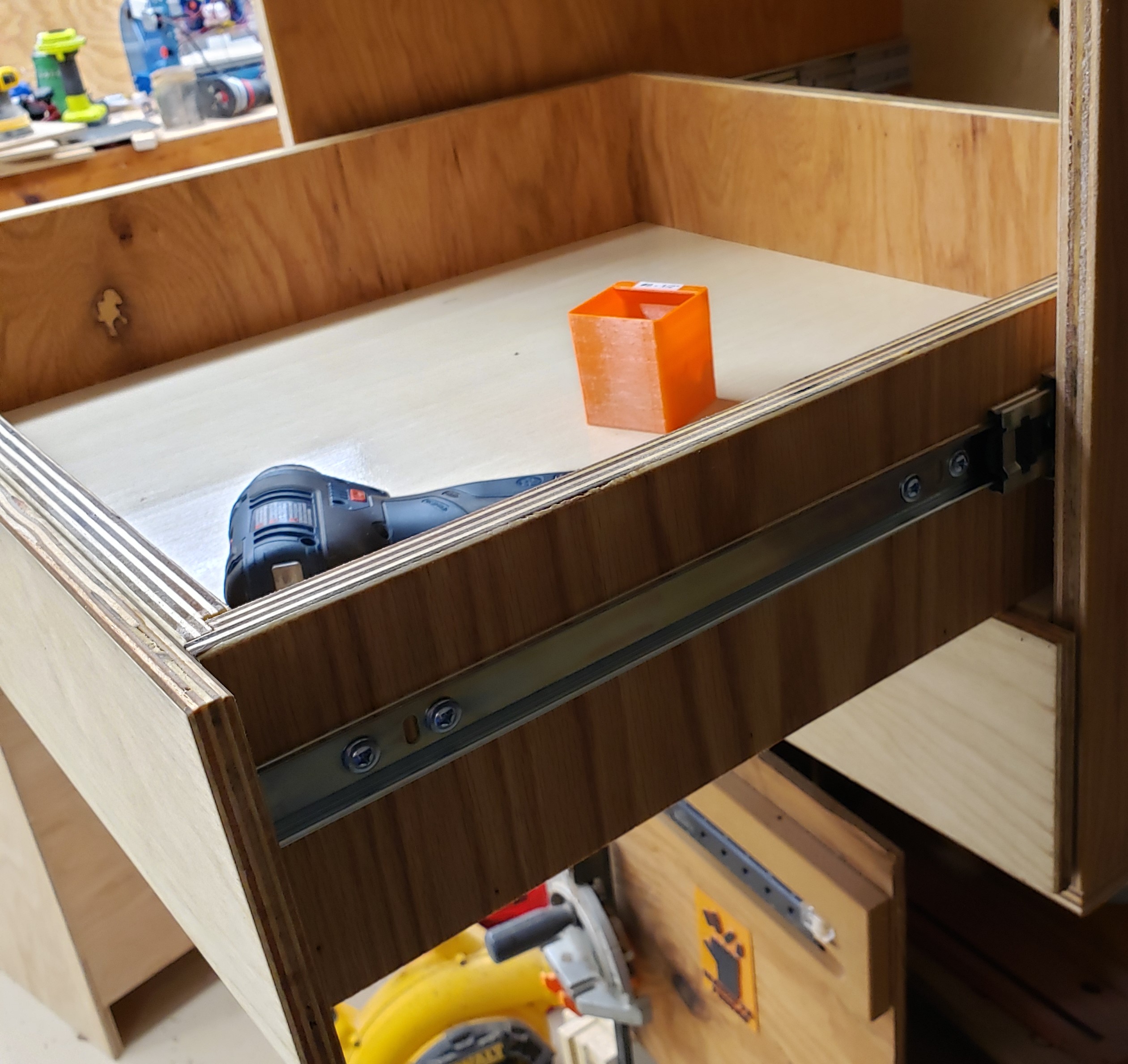
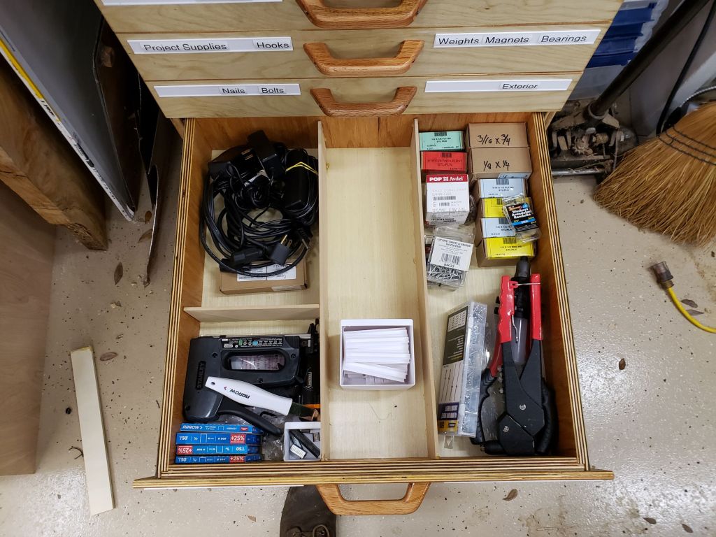
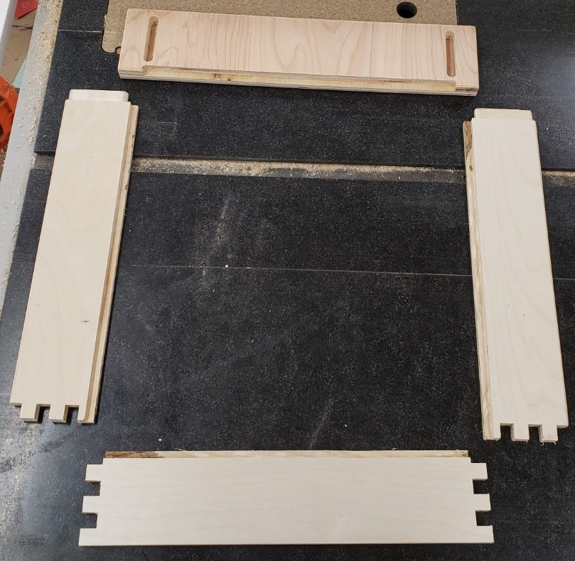
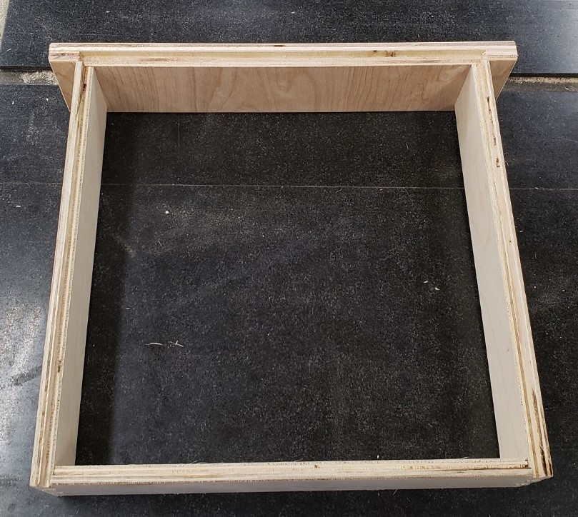
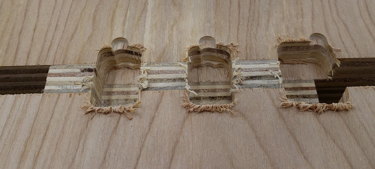
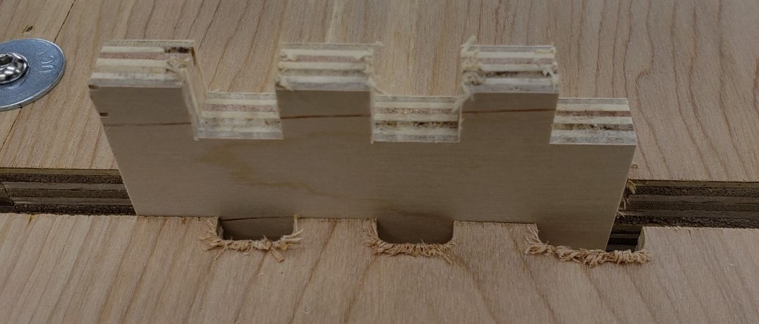
What kind of drawers are we talking here? Nothing too fancy, but I wanted the ability to make finger joints without too much fuss and setup. I’ll leave the details of the joinery and lessons learned for another post. For now, this one has finger joints on the back, and a tenon into the drawer front for the sides. Hidden and very strong.

Jig V1

The first jig was a pretty simple setup. I attached a piece of plywood to the front of the mill table to align boards vertically to the table. It was square to the top and had cam lock clamps to hold the board in place. Sticky backed sandpaper provided secure grip on the table side and on a clamp board. I had a double layer of plywood screwed down to the table behind the board to back the cut and a plank of 1/4″ MDF on the font. This gave both sides of the cut support to prevent blowing out any drawer side pieces.

Clamped side in place

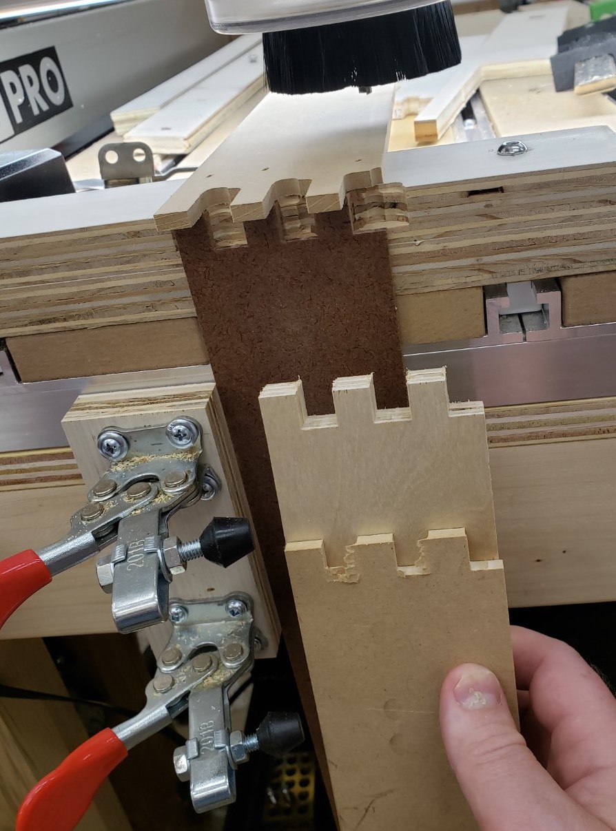
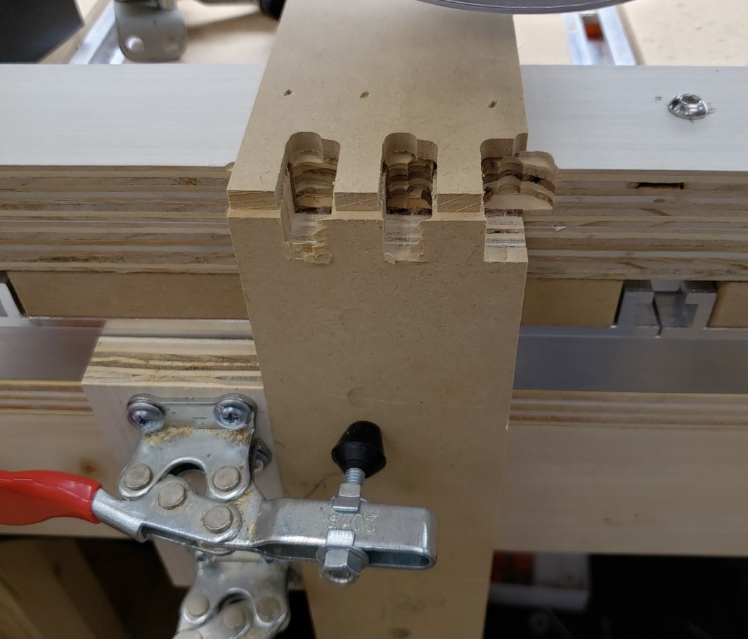
With this setup you could repeatably clamp a board in place and usually get a pretty good cut without too much fuss. Replacing the backer was a huge pain, and the top stop was only good for one shape. It worked for my first 3 drawers, but after that I stopped to think of something better.

Joinery Jig V2

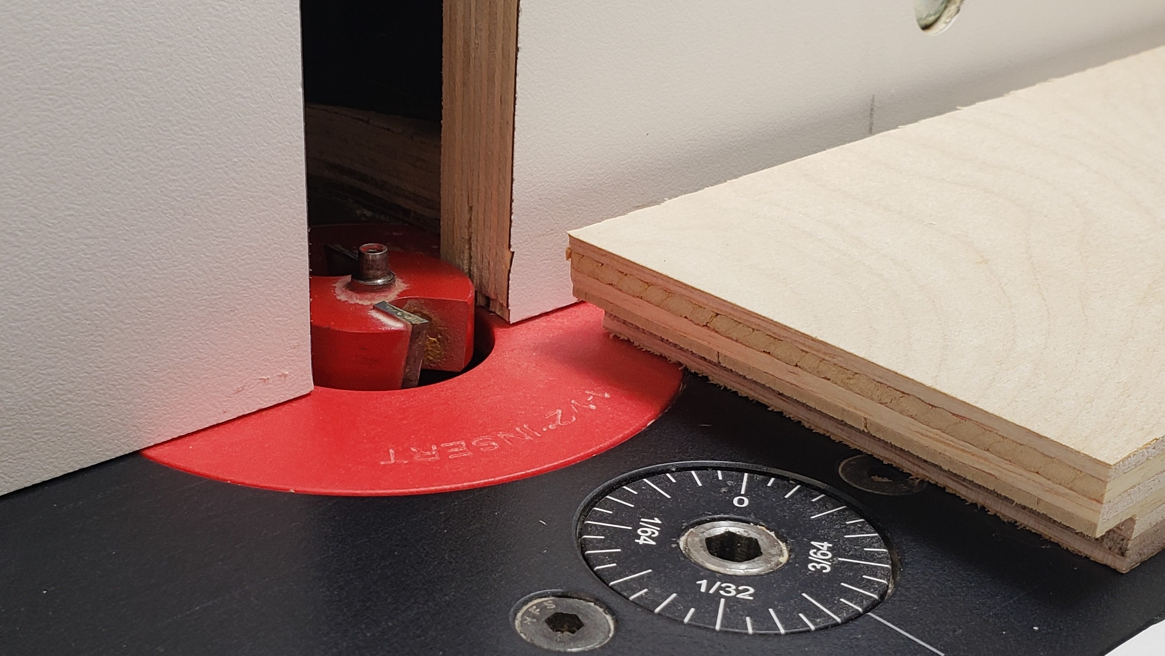
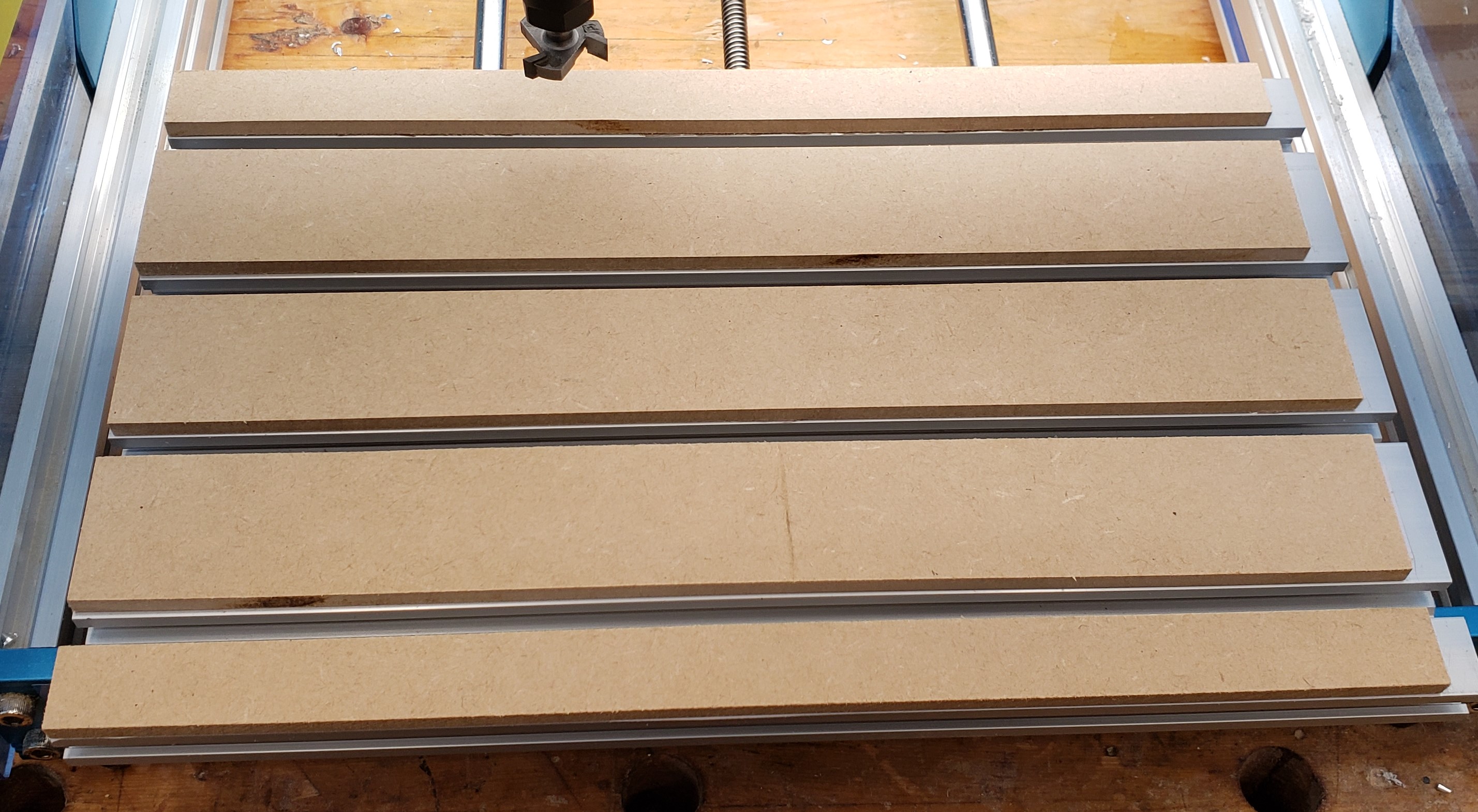
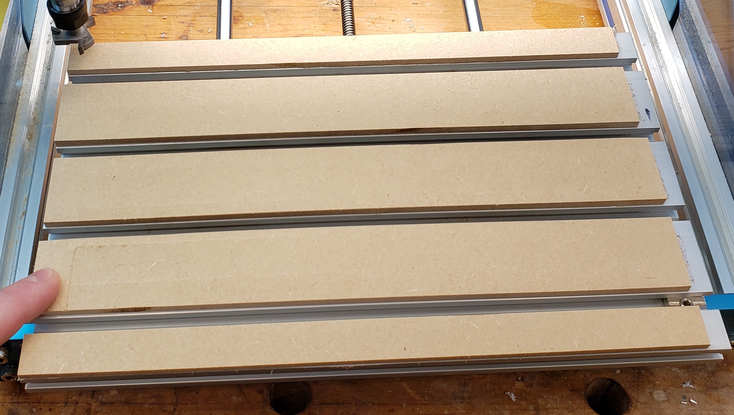
The next version has a two half system. The back half bolts down to the table top while the front half slides and clamps the board to be processed. There are sacrificial inserts that back all of the cuts to prevent blow out. Those are held in place by two clamp bolts on either side.

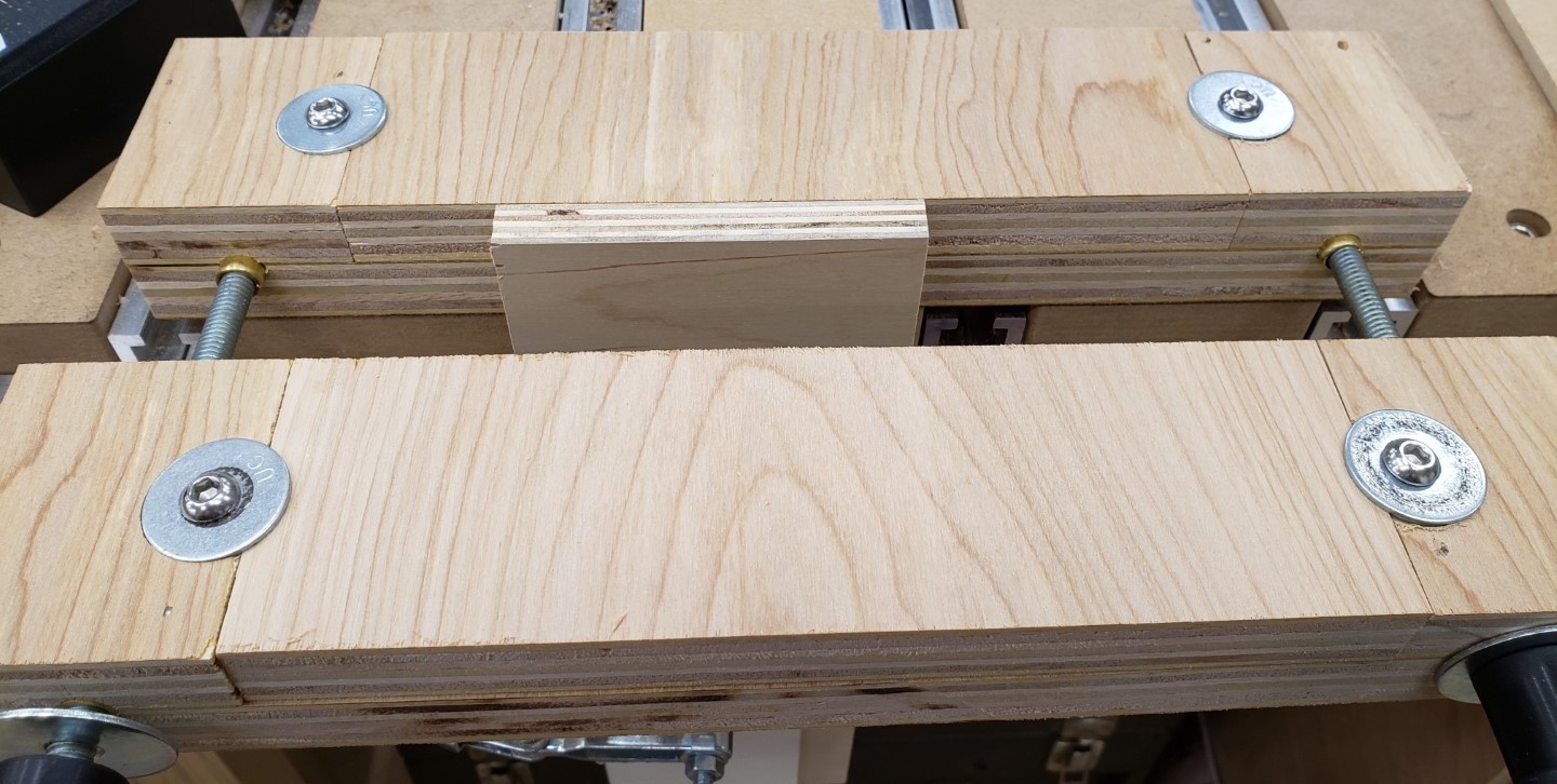
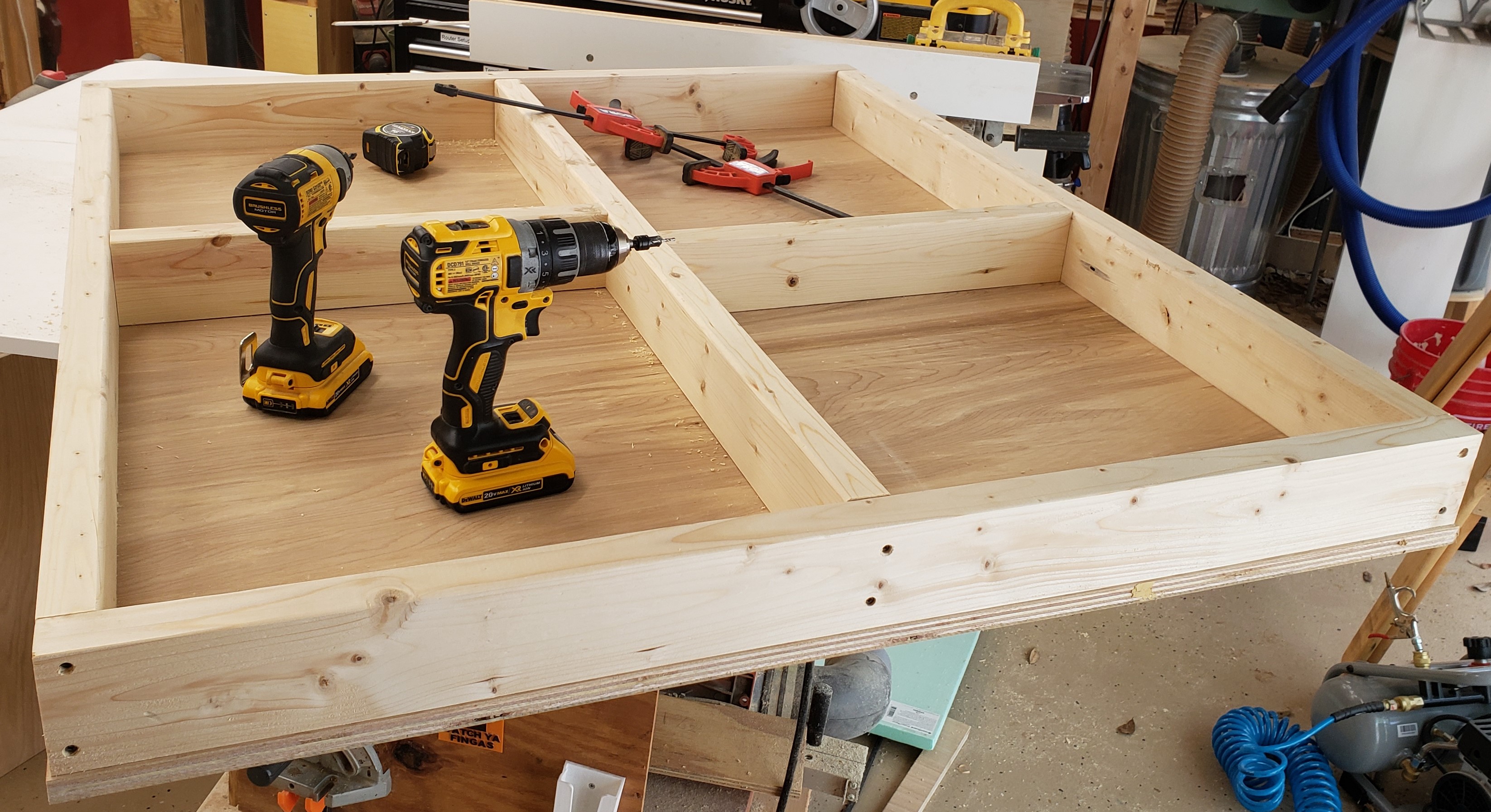
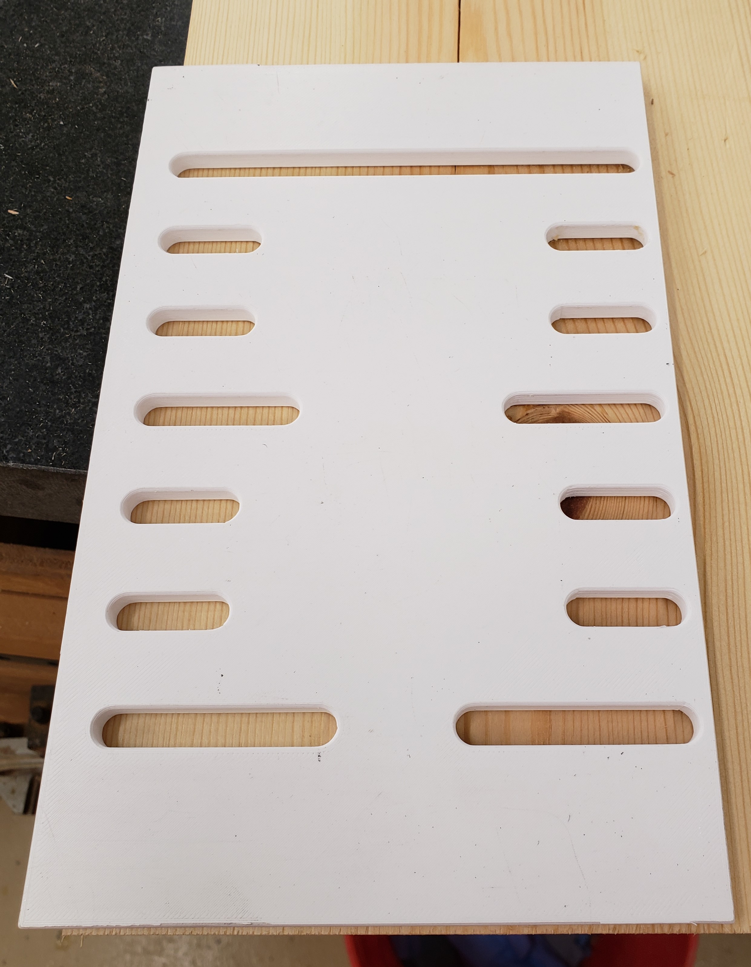
To create the jig I attached two pieces of 34″ plywood to the outside edges of a larger piece of plywood with glue and nails. This would be the base area for the rails/bolts that clamp the two halves together. I will mill it all as one piece and cut it in half at the table saw.

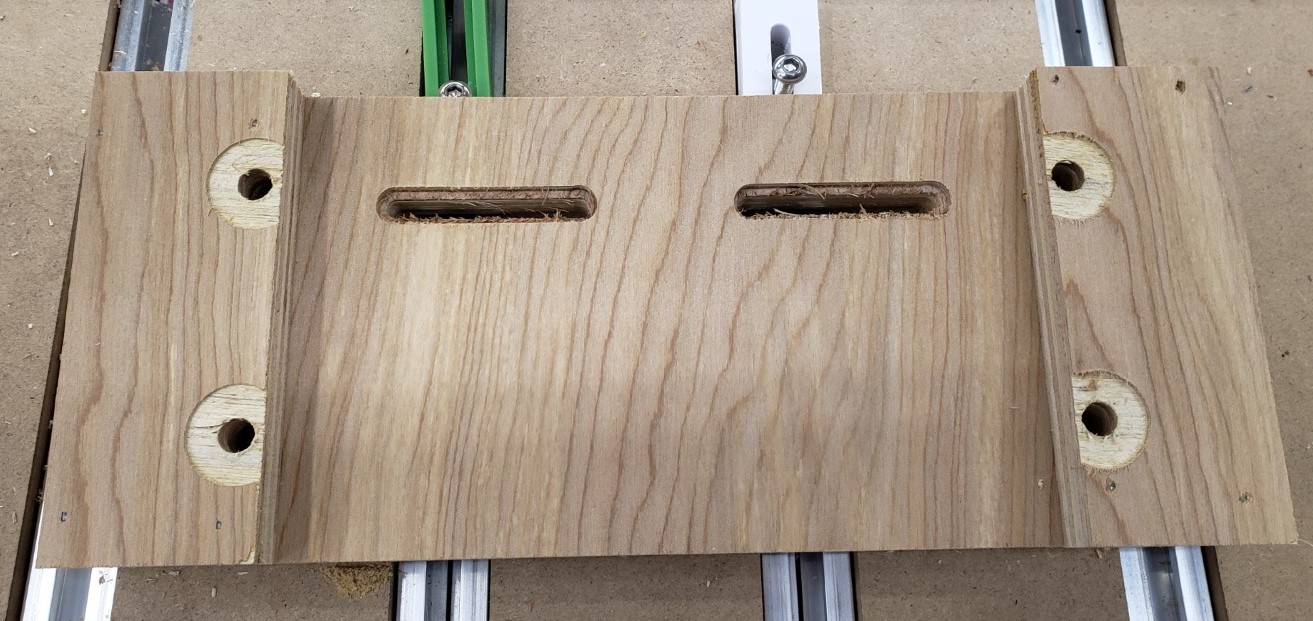
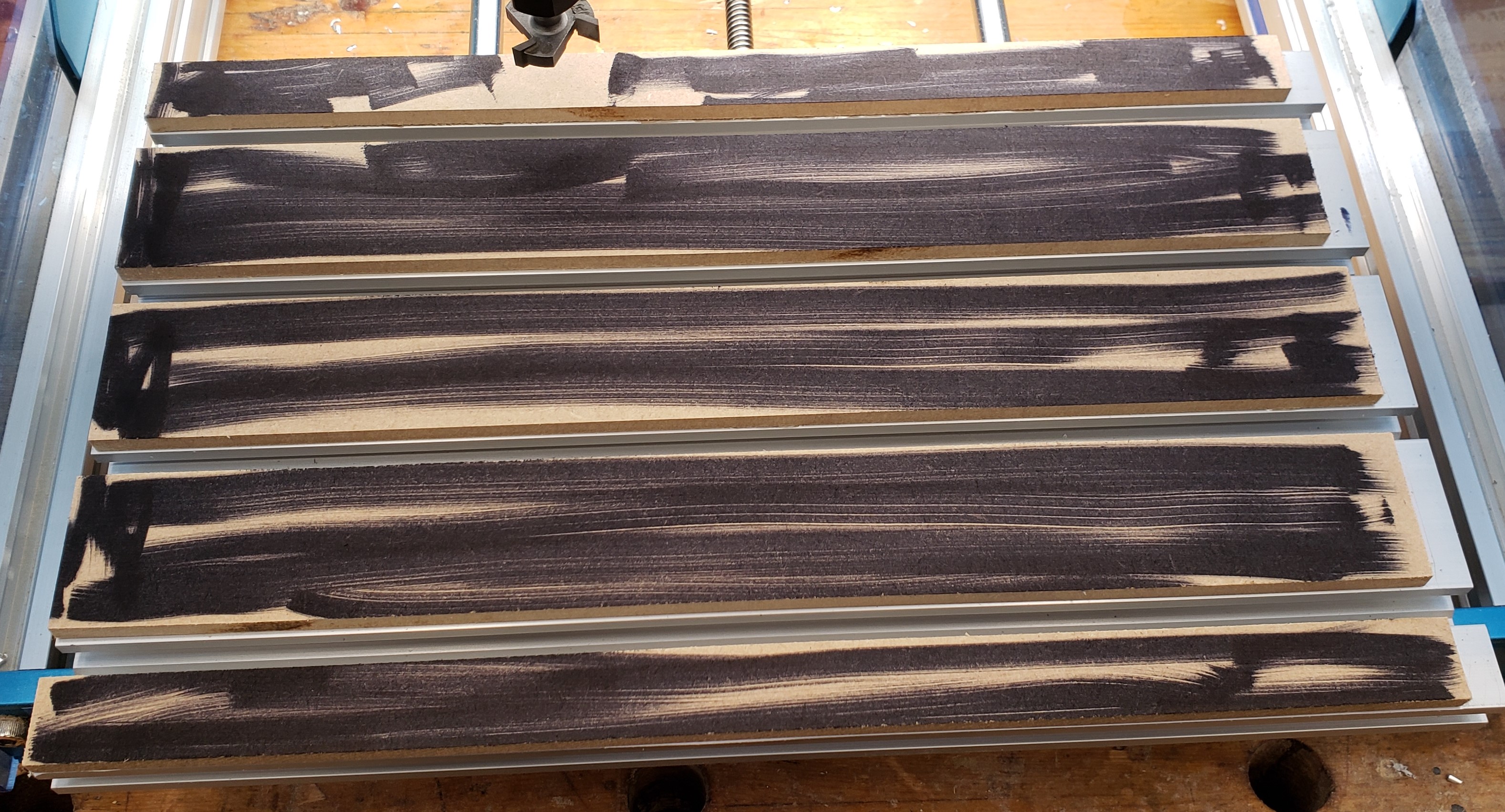
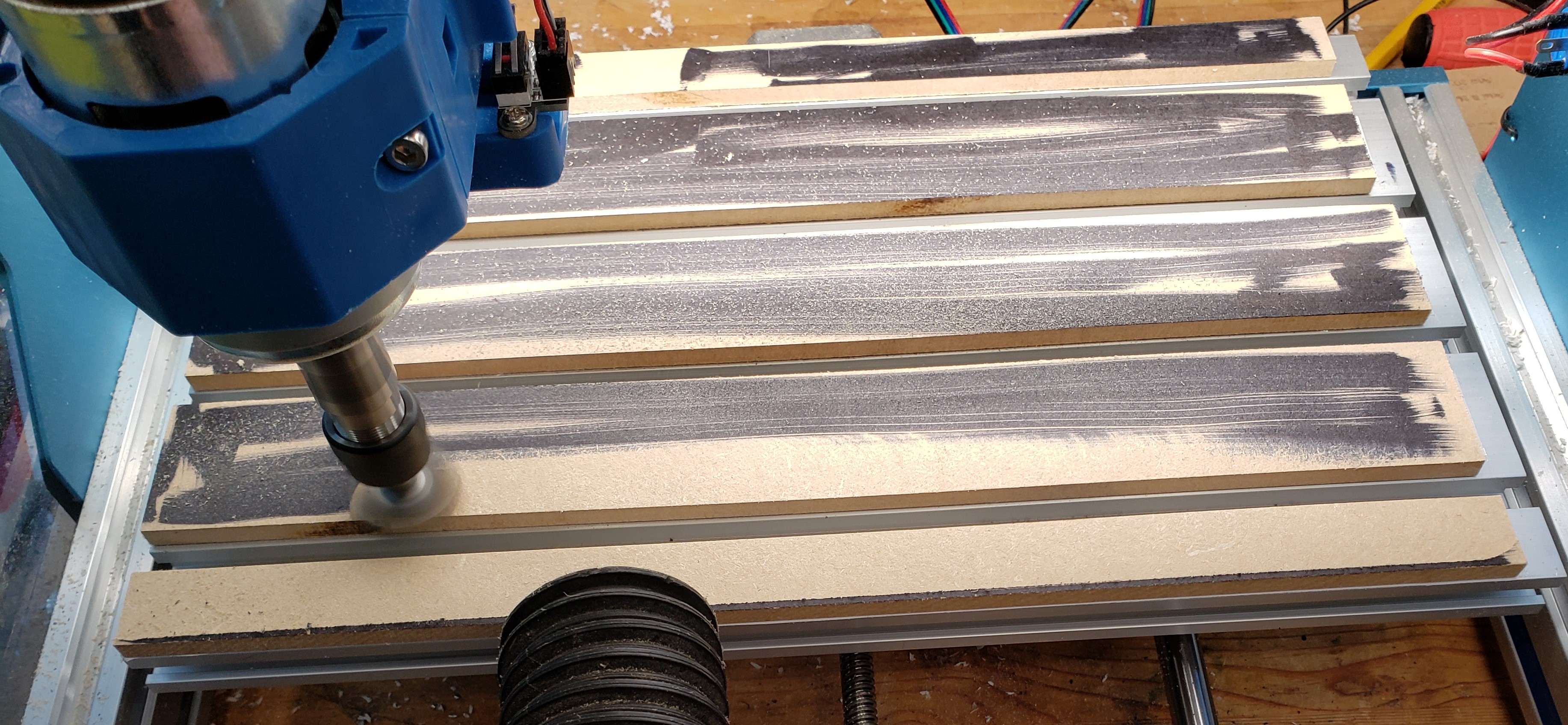
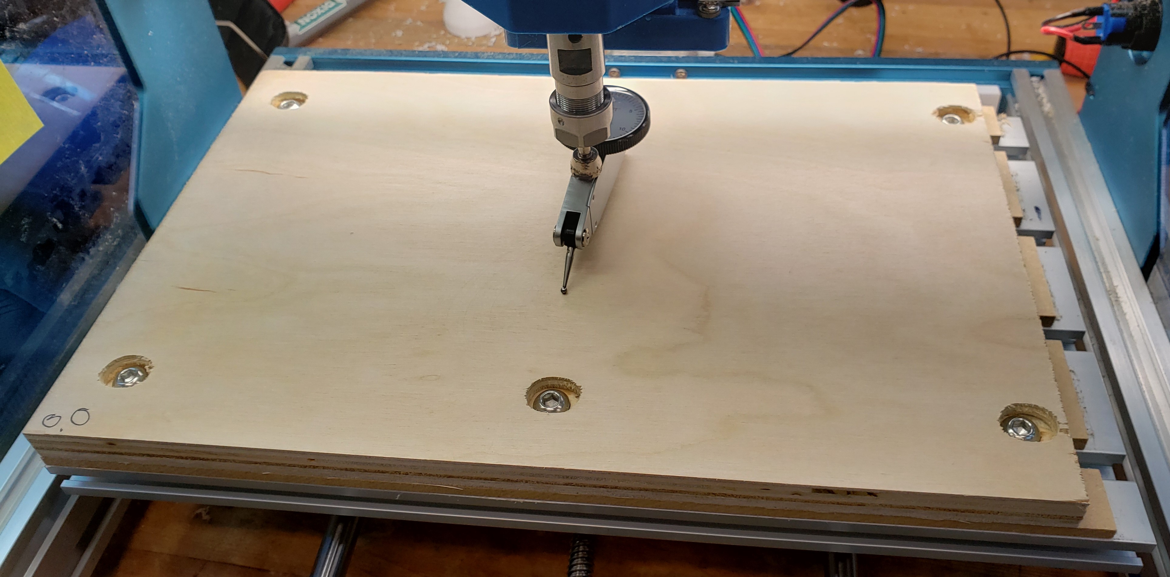
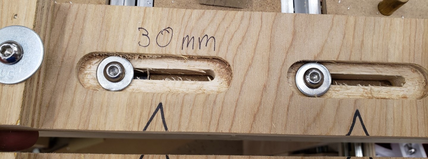
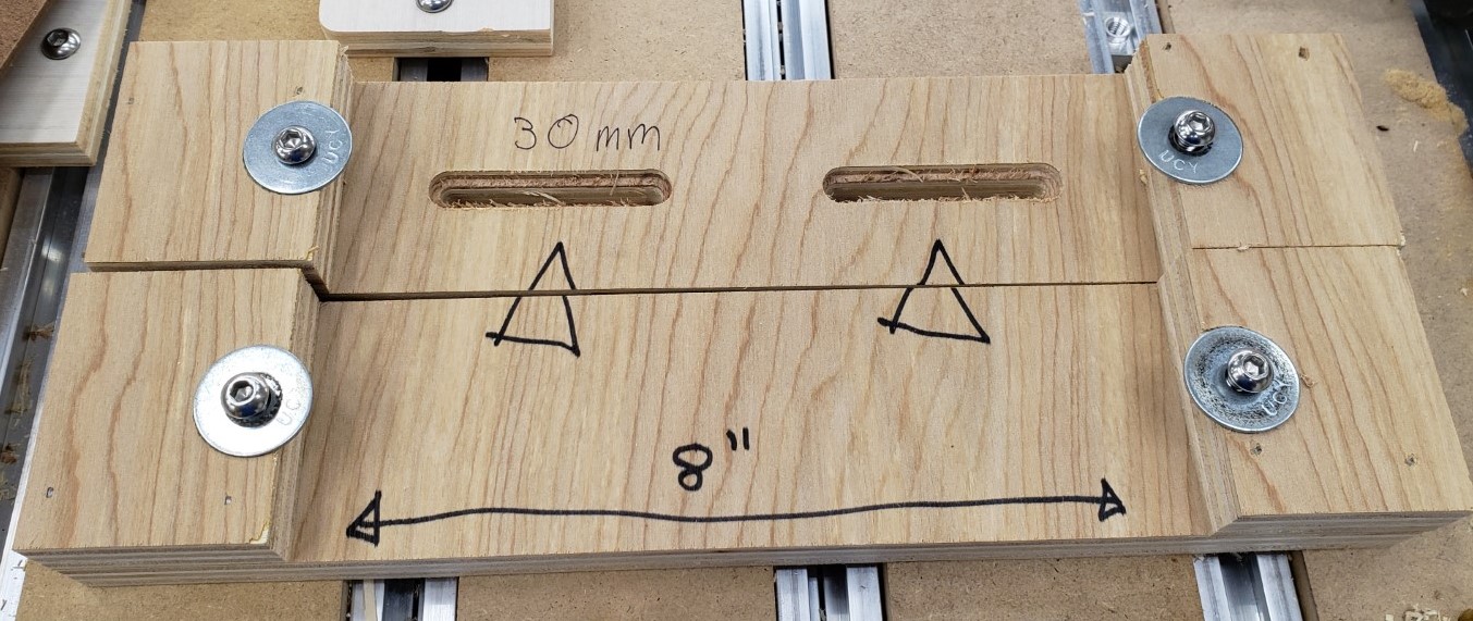
The slots are 50mm long and spaced 100mm apart. That should let me position it anywhere on my table top by always spanning two rails. I started with them just wide enough to hold the bolt head, but eventually widened them to allow washers. Bare screw heads on plywood would eventually compress and allow the jig to rotate.

Widened to allow washers

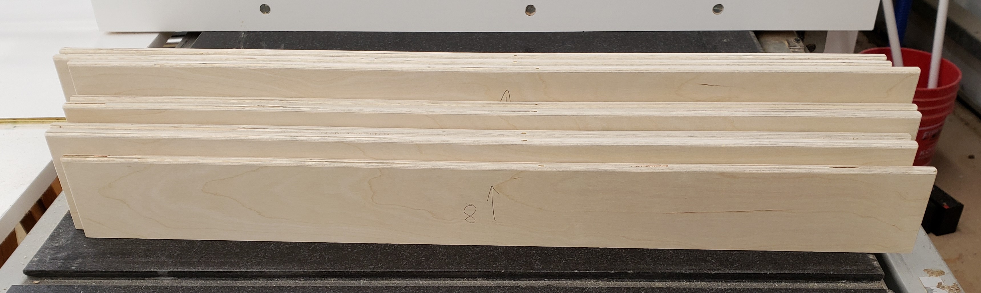
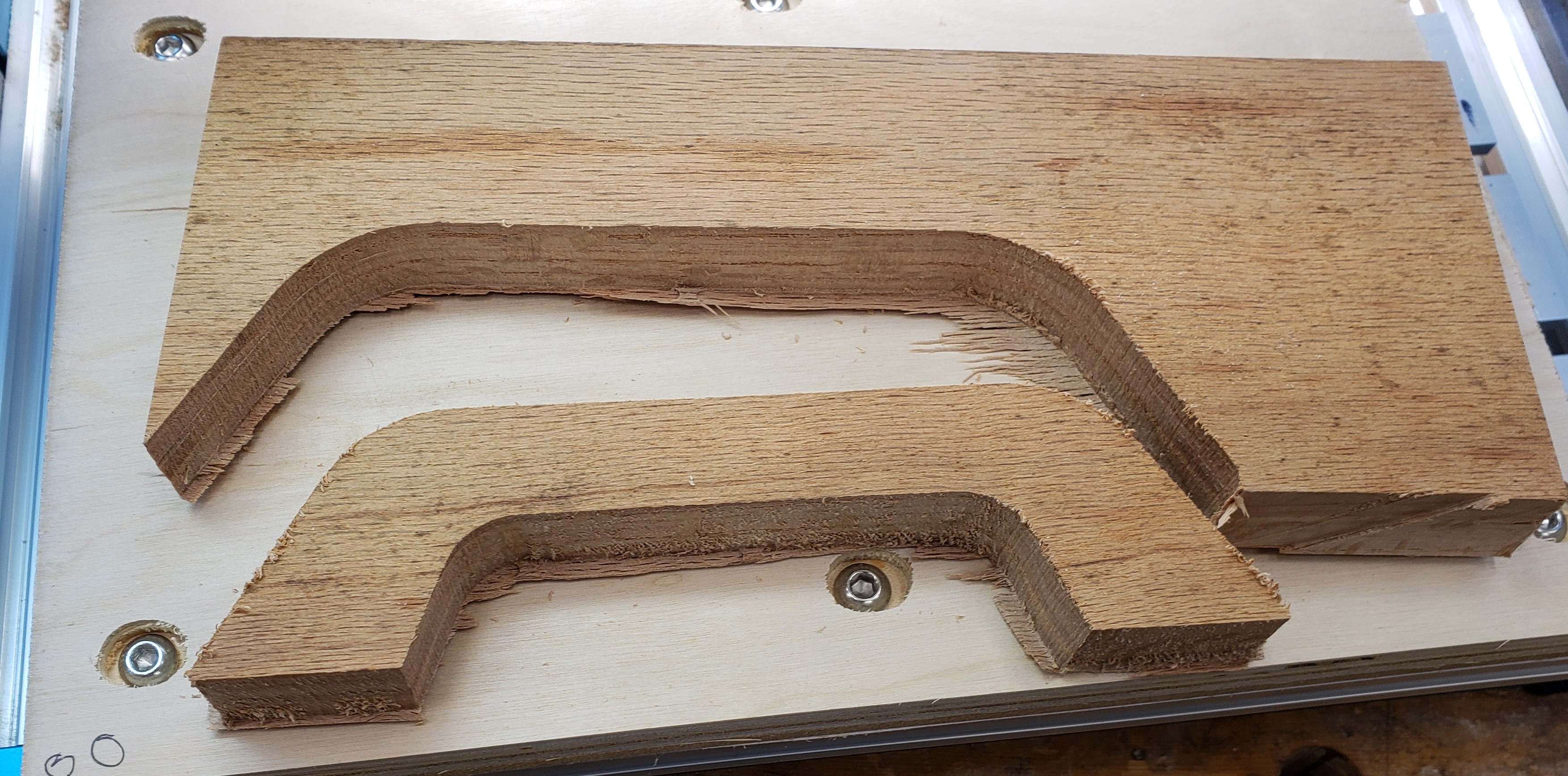
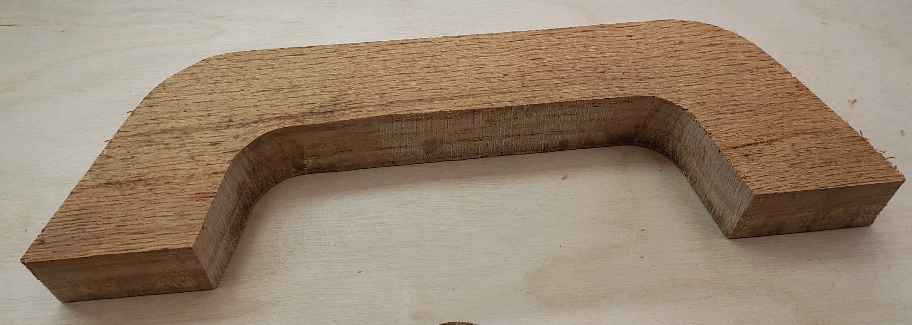
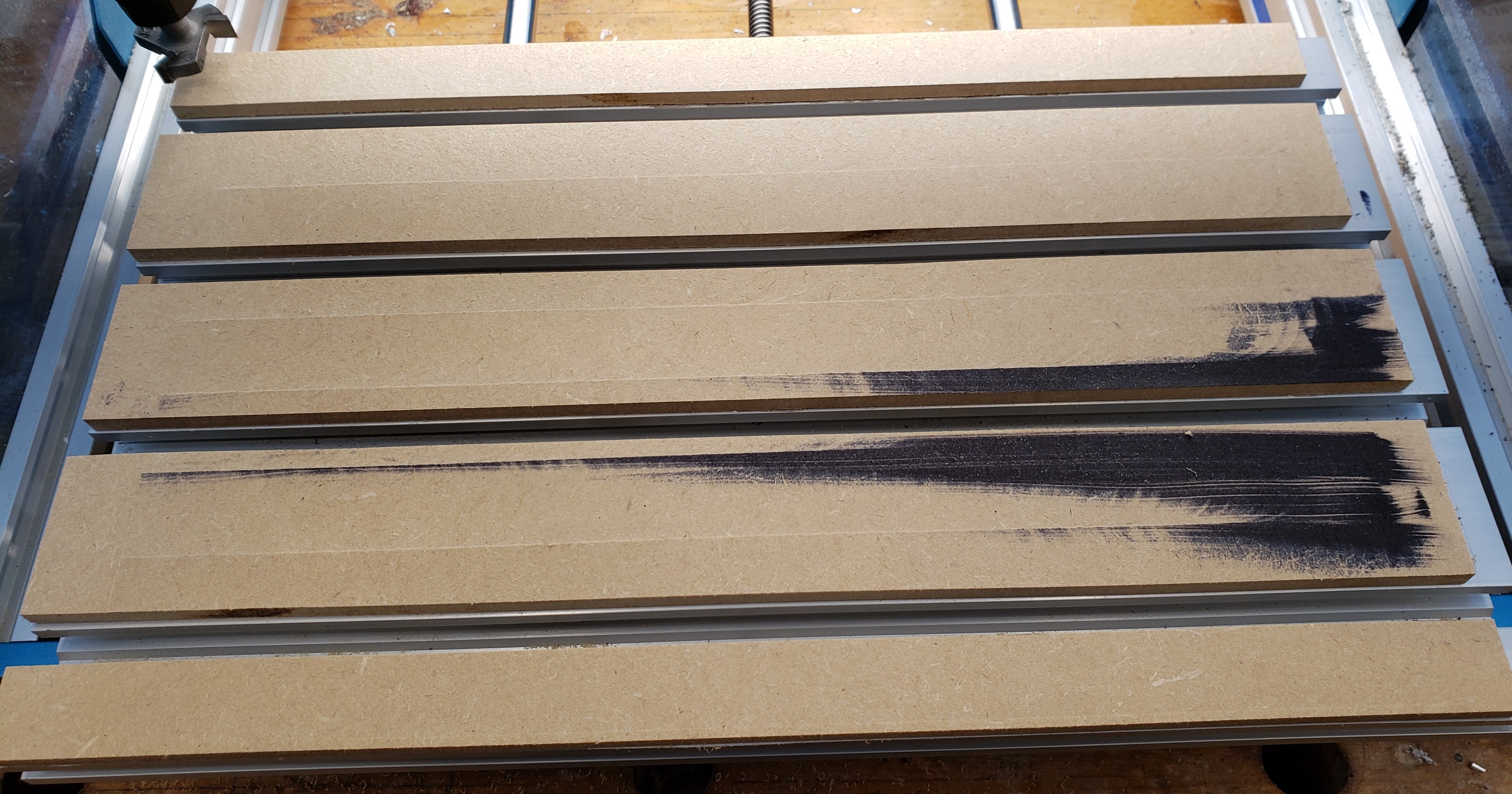
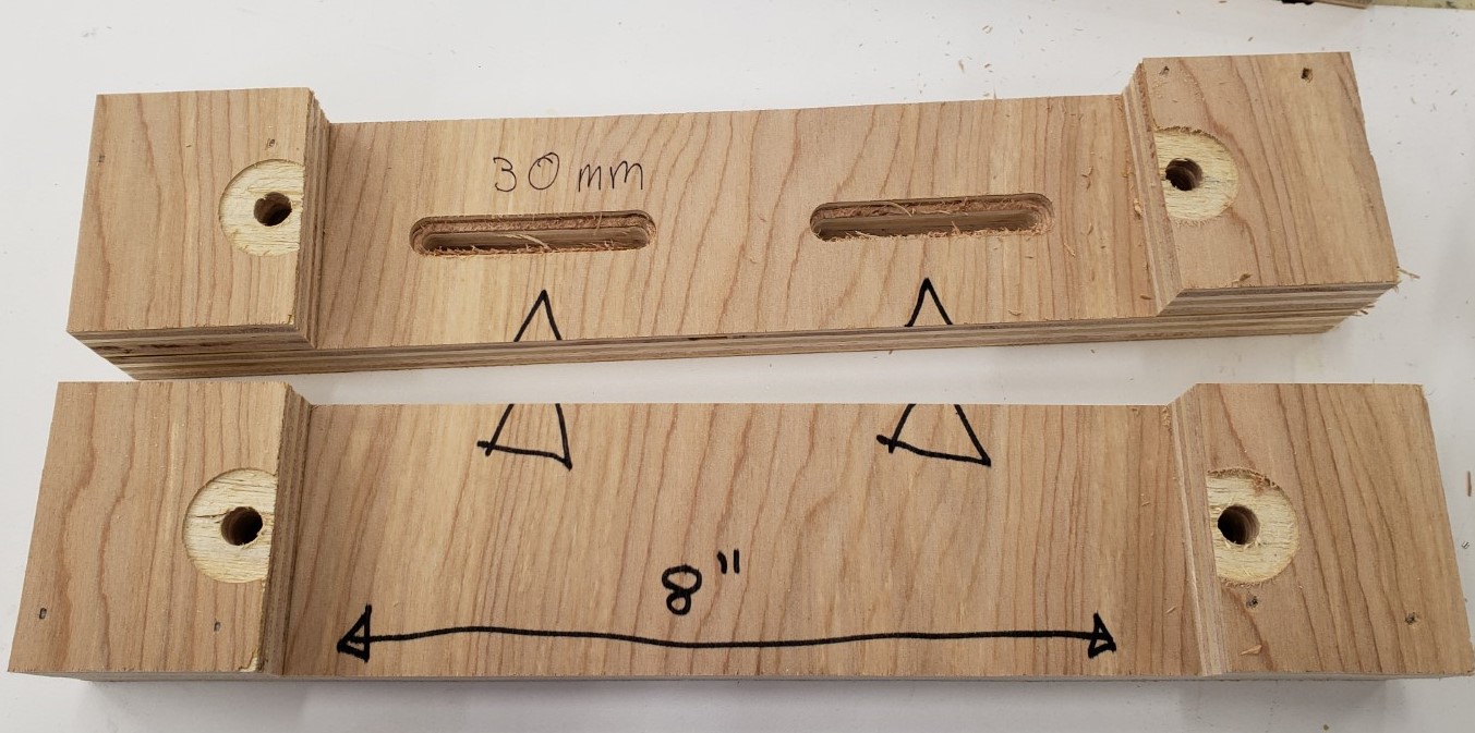
With the milling done, I cut it in half at the table saw, then added some alignment notes. Any 8″ wide piece of 3/4″ plywood or MDF should clamp in there.

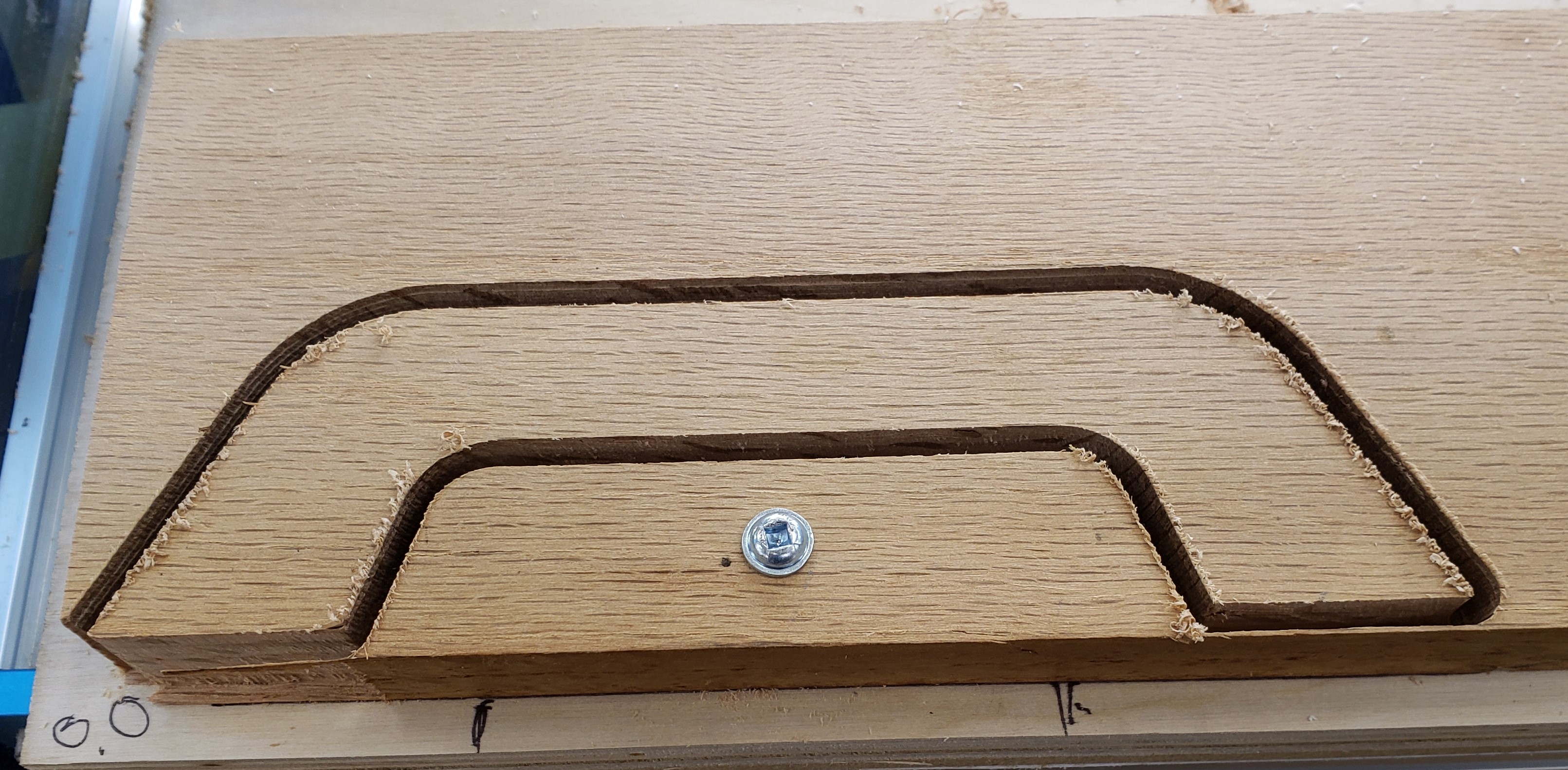
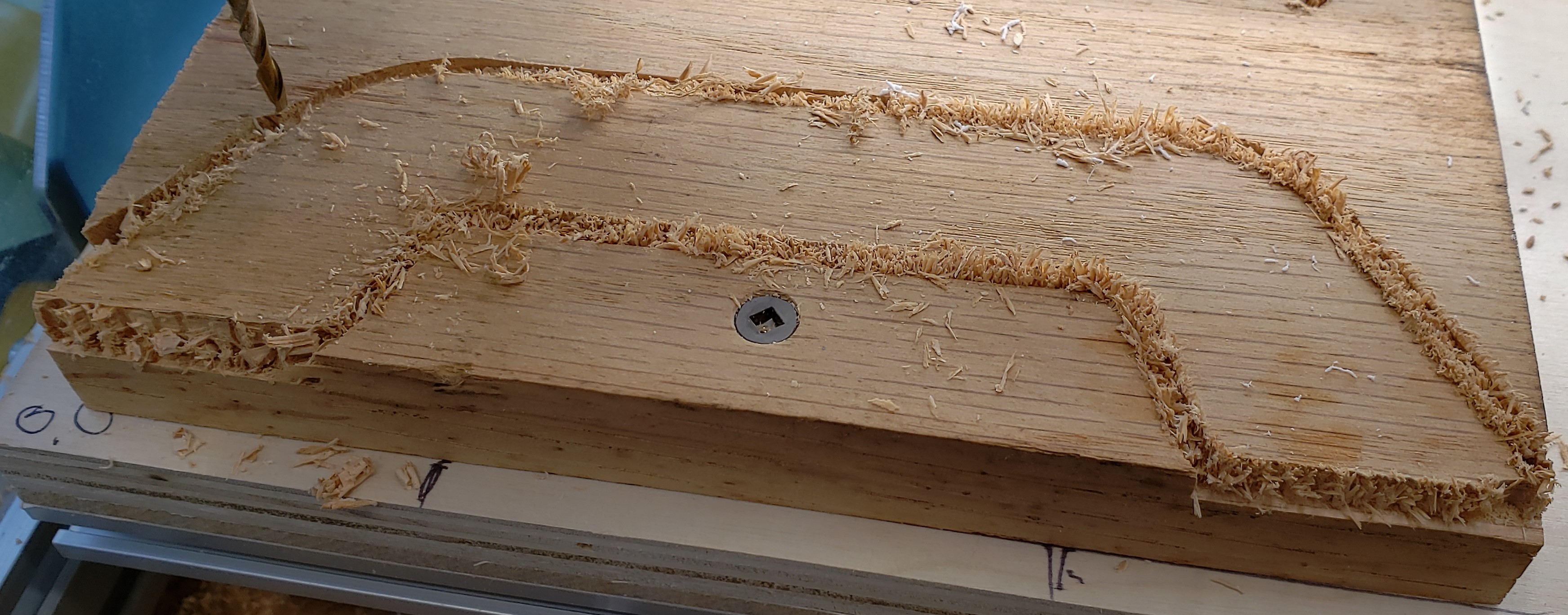
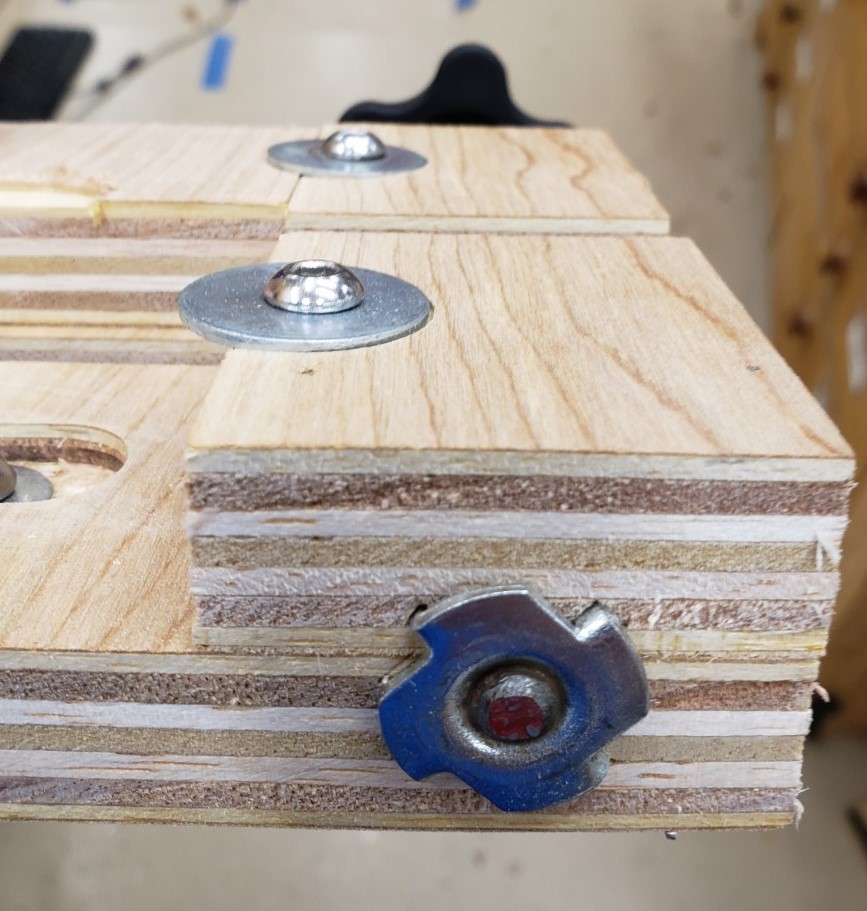
To hold the sacrificial waste blocks I screwed in an M6 threaded insert to the bottom of the jig. Button head screws and fender washers sit in the counterbore and clamp down the waste boards.

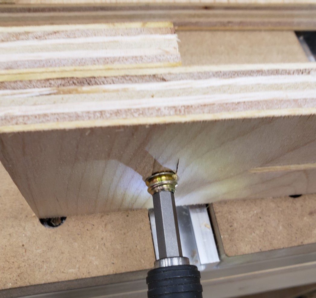
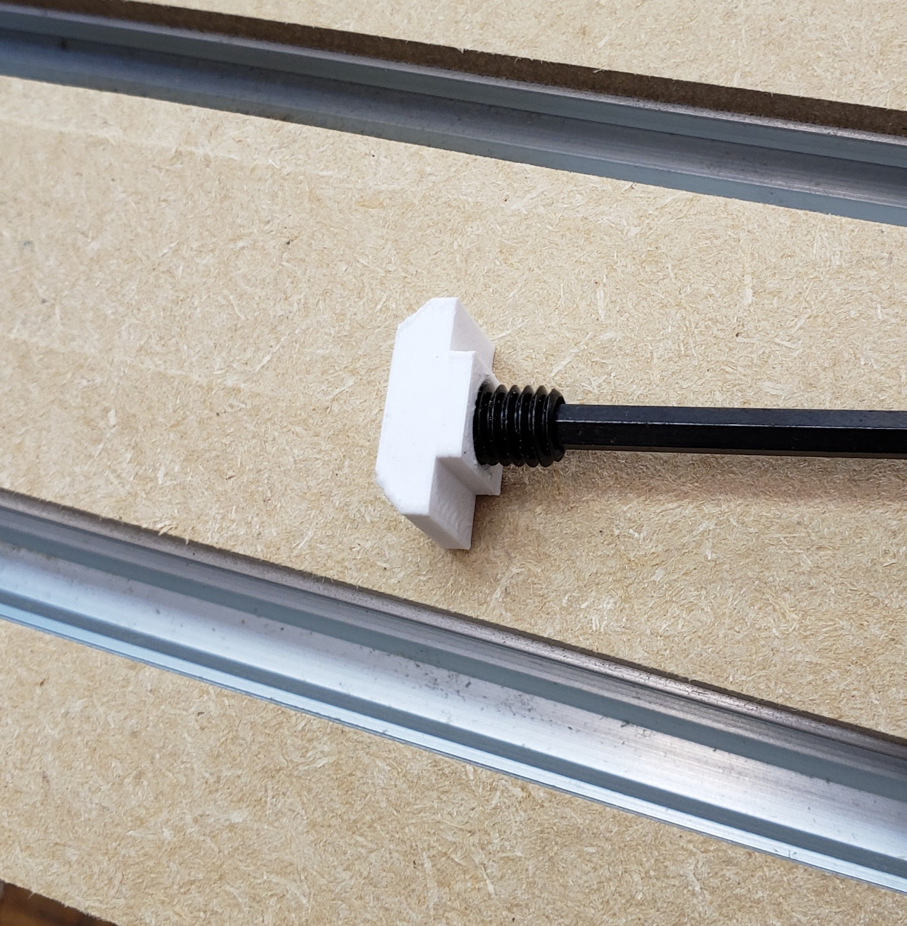
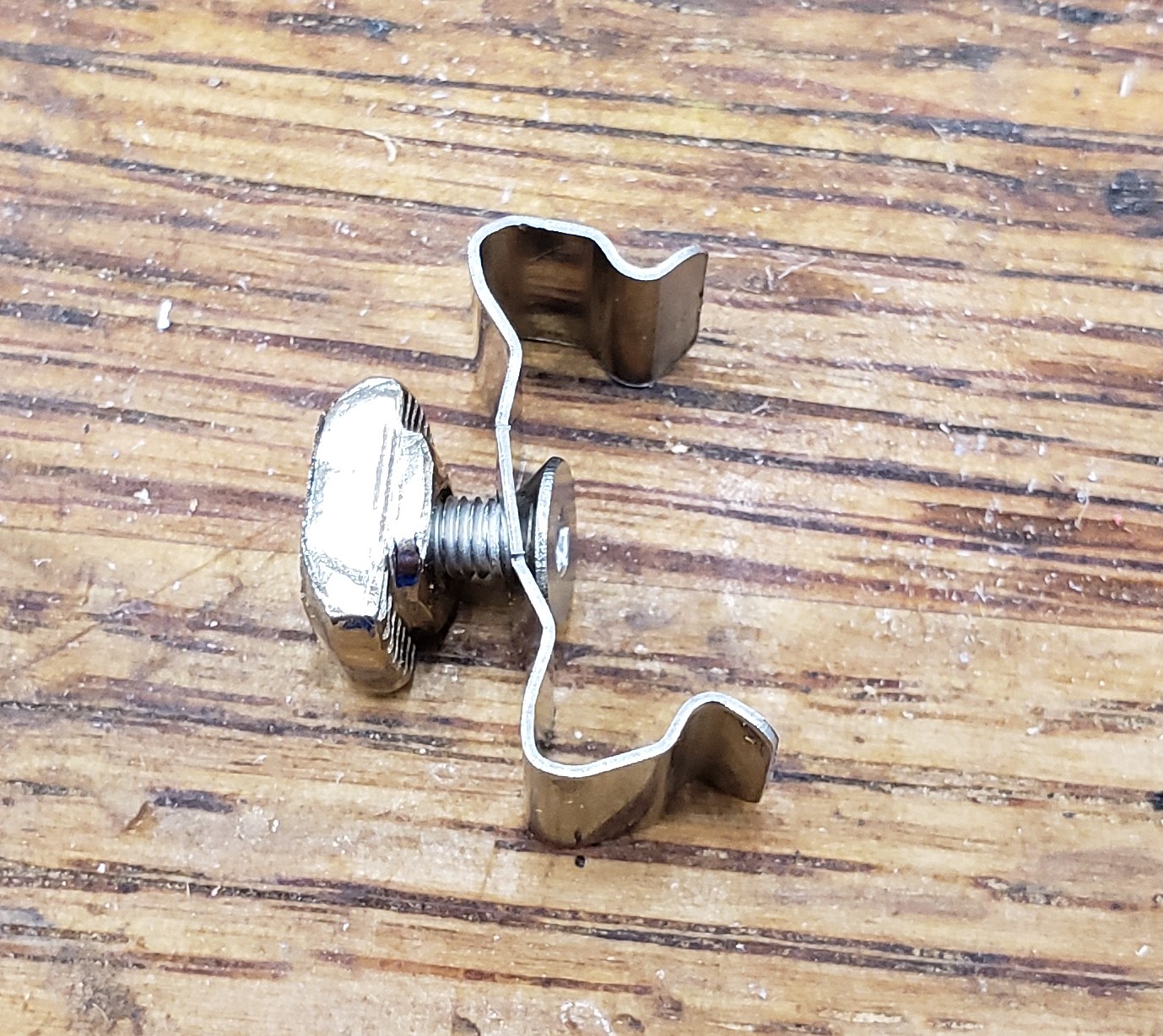
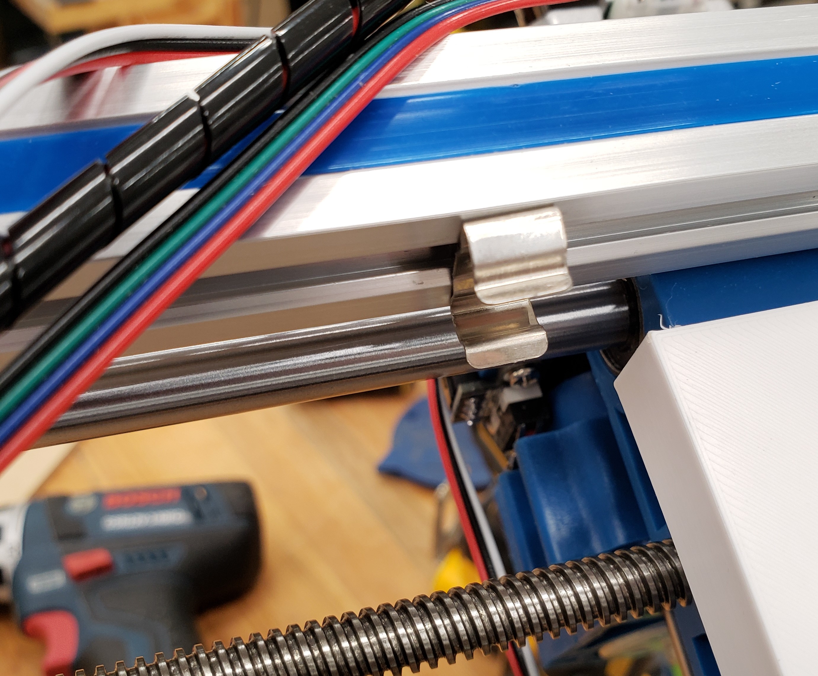
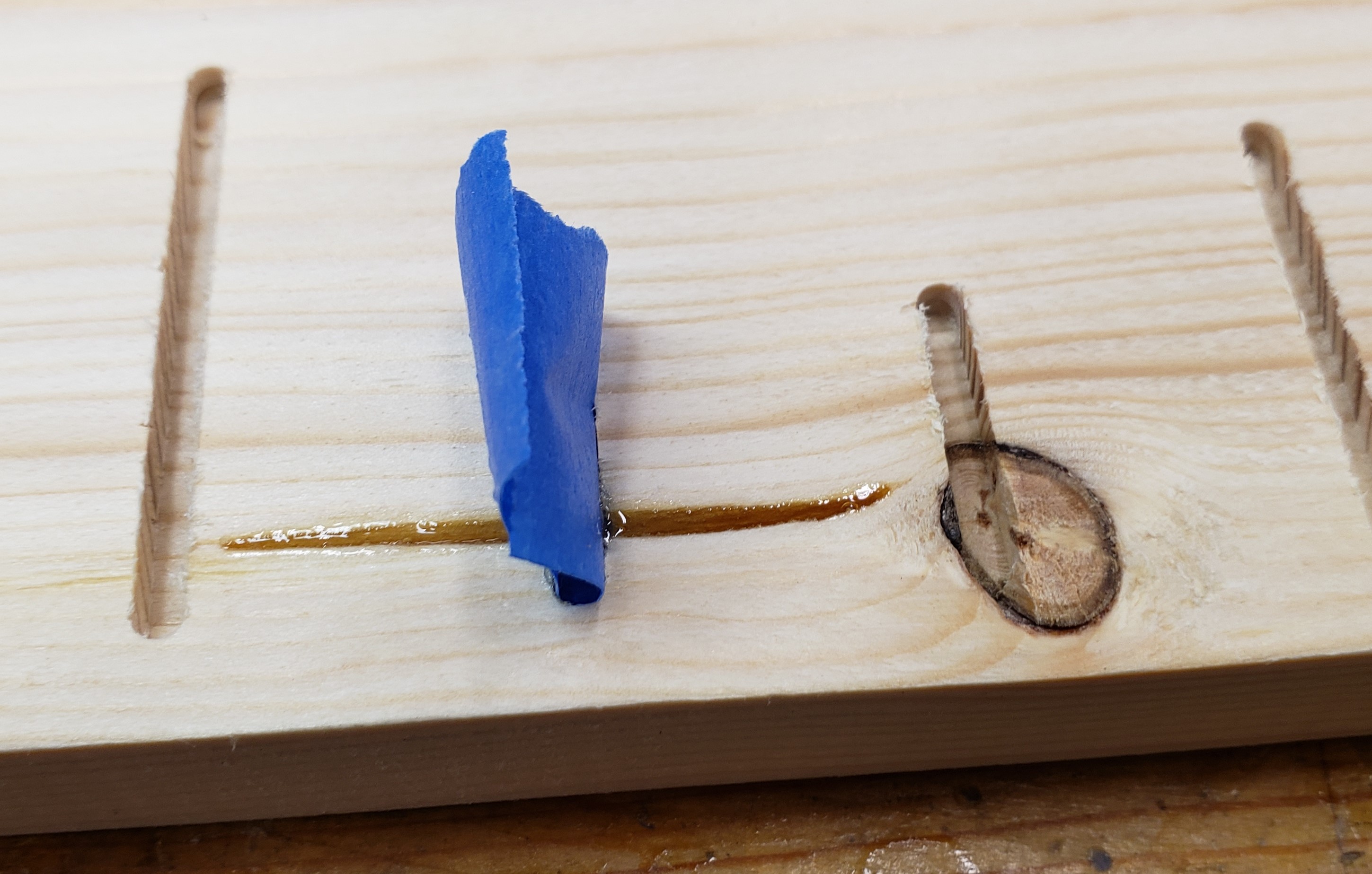
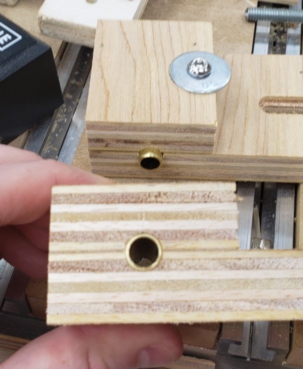
I clamped the boards together and drilled all the way through with a 3/8″ bit. It gave clearance for a 5/16″ t-bolt hammered into the back, and brass tubing in the remaining spaces. This acts as a bushing for the 5/16″ bolt. I used thread locker to keep it secure in the back, then large knobs in the front to clamp everything down.

T-nut secures 5/16″ threaded rod

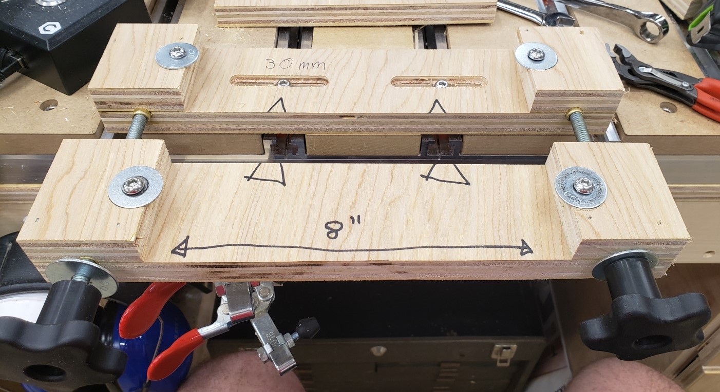
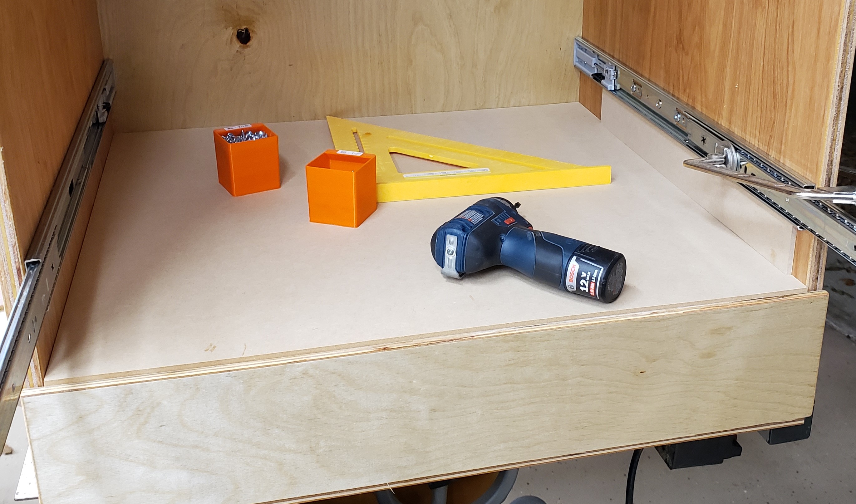
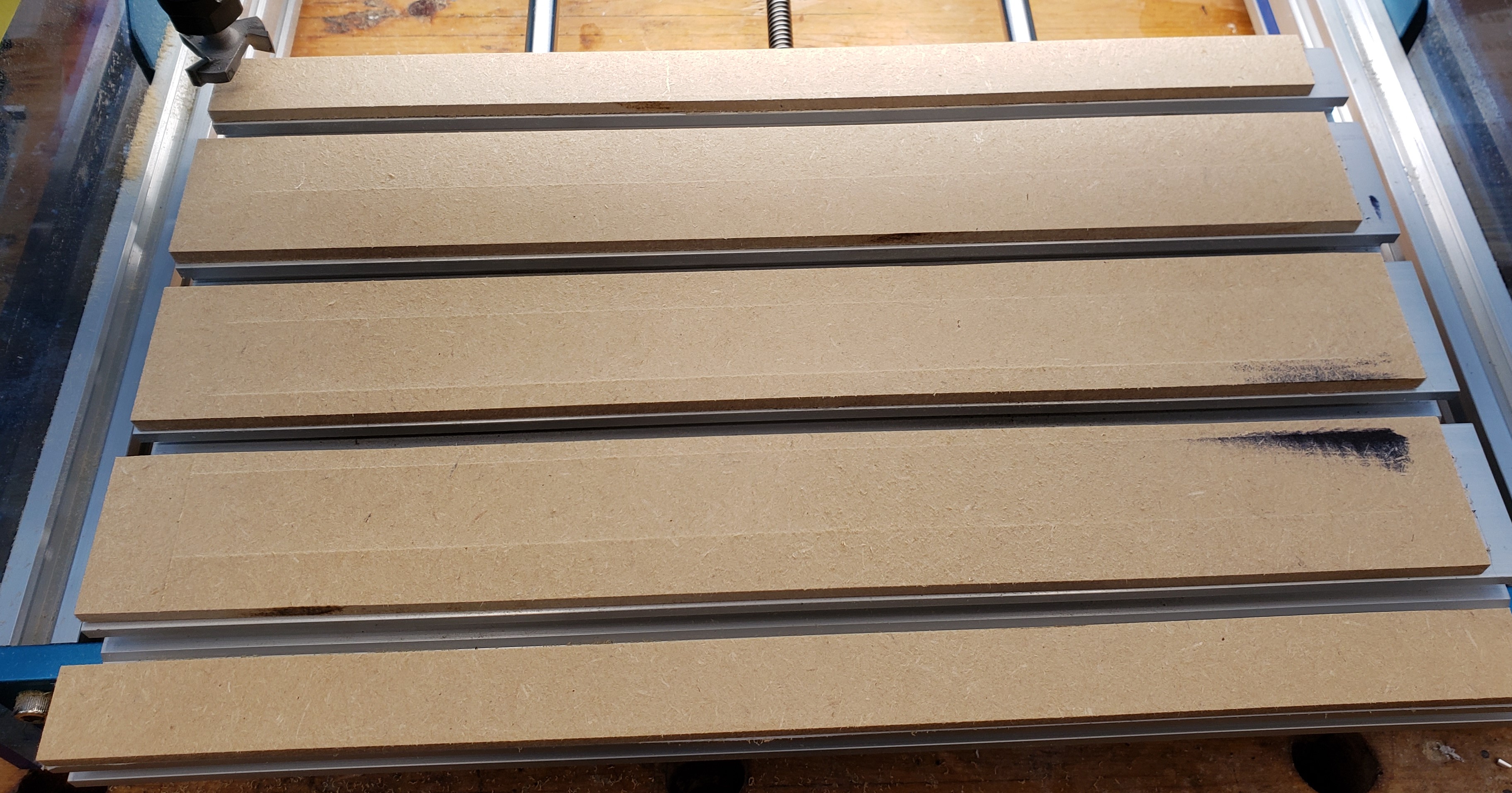
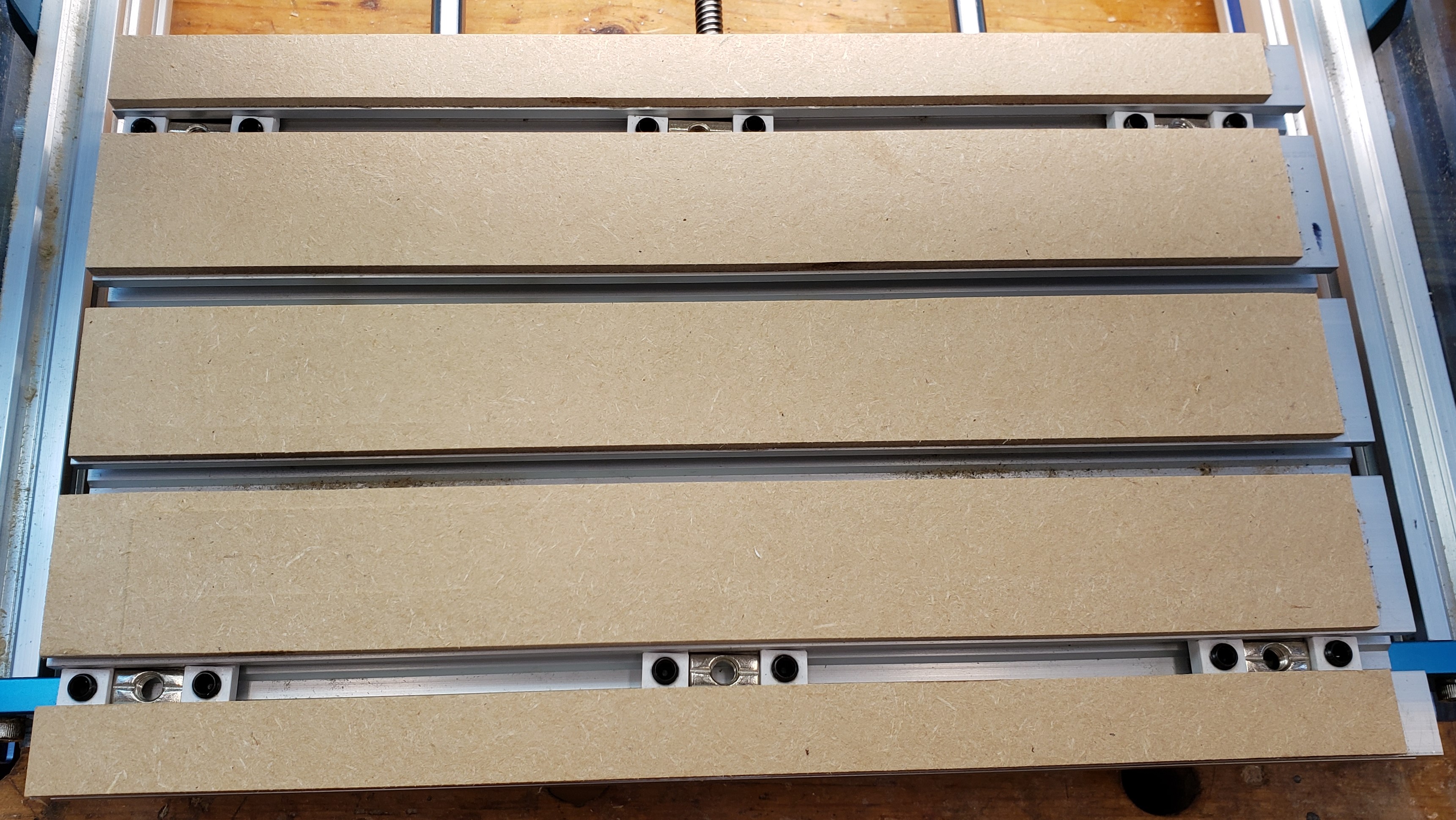
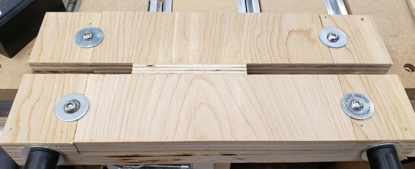
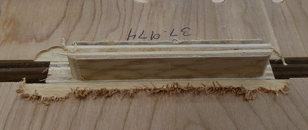
Here it is fully installed without the waste boards inserted yet. You should be able to get at least 2 uses out of a 3″ wide waste board by flipping it around after the first cut pattern. I found mine were in good shape even after making 16 cuts of the finger joint pattern.

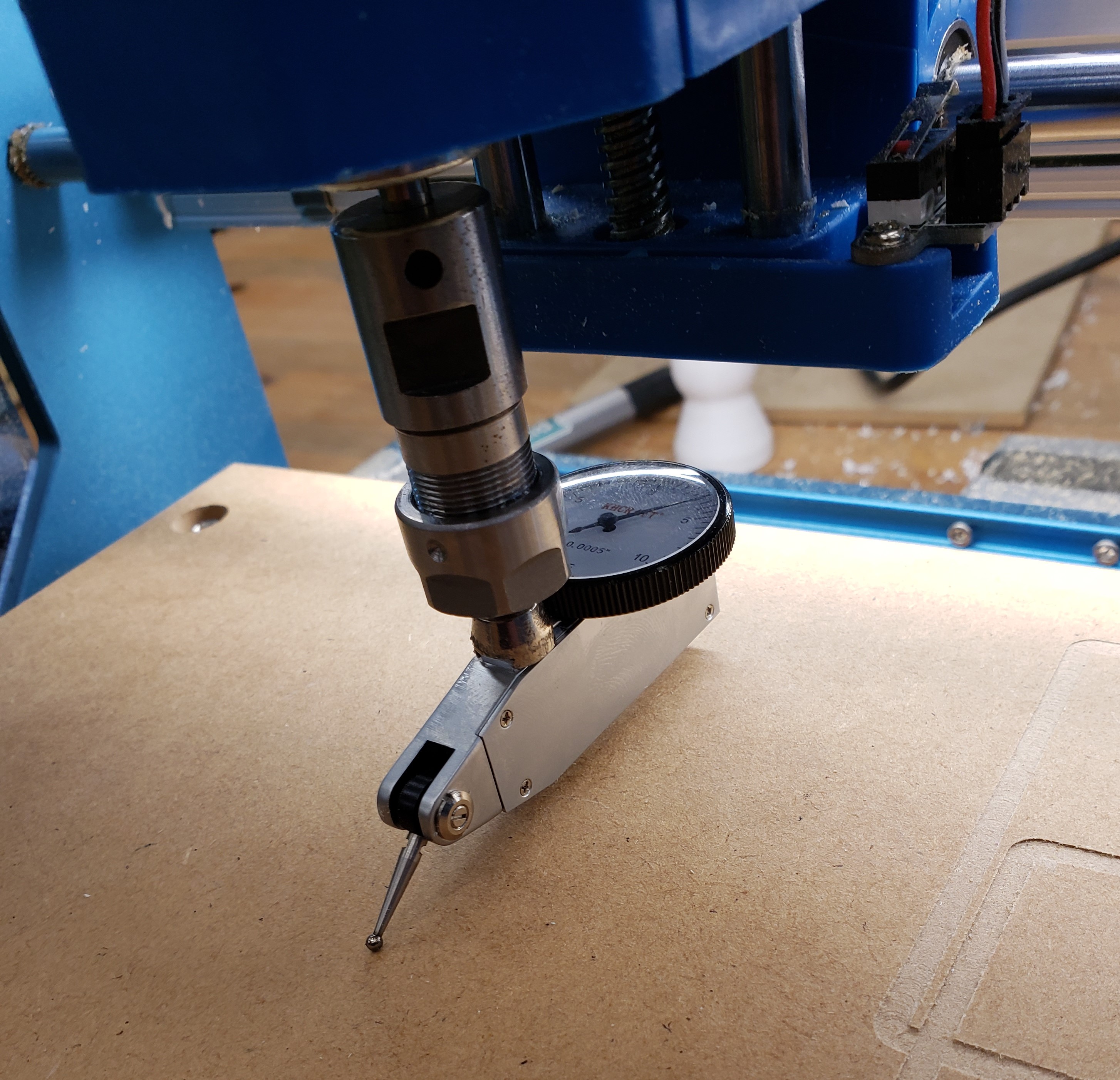
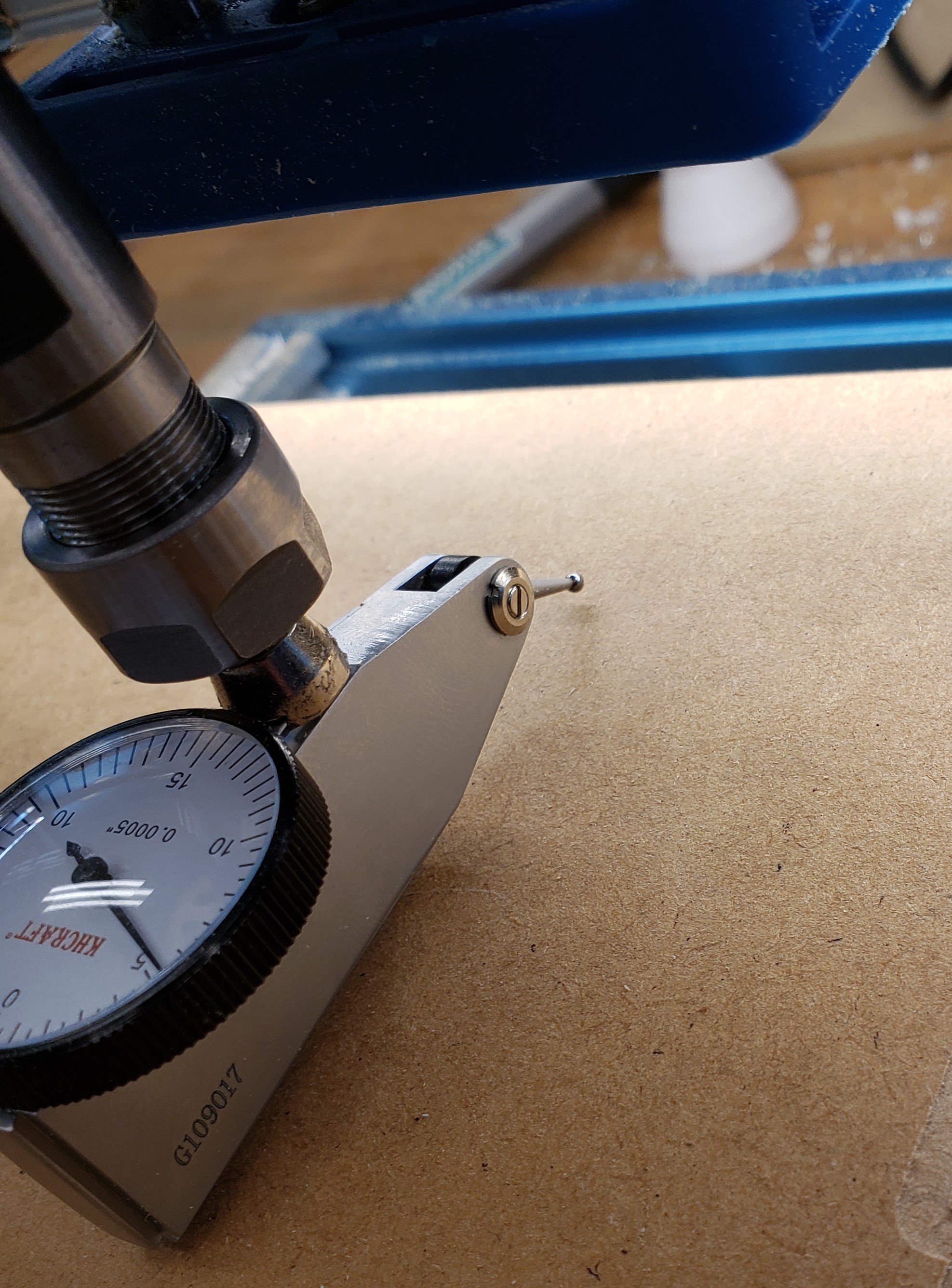
This version doesn’t need the cam clamps, the vise like action of the two threaded screws has plenty of clamping power. Similarly, I didn’t need a height stop. I could very accurately feel when the board was flush with the top of the jig. The second round of drawers went very smoothly with this jig!

New Router Mill and Table

After months of messing with my 3018, I am upgrading to a shapeoko pro. Having owned a shapeoko 2 many years ago, and gained a new appreciation for the power of modern CAM software available to the hobbiest, I was ready to jump in deep. A recent engineering award at work sealed the deal by adding a monetary boost. The 3018 was fun, but kind of a toy. I struggled to get my projects to fit on it, and it was barely able to slog through the oak handles on my material cabinet.

The new tool is a big beefy bad boy! So big in fact, I had to use a toddler for scale. He is 32″ tall, and this thing can cut a 33″ square. Everything about it is designed very stiff compared to any of my previous mills, and I think to get something better would require a custom build or doubling the price tag.

A big CNC router requires a big table. I moved a lot of shop things around in my head until I decided I could actually fit this beast. My woodworking bench had to scooch over a smidge, but there was room, and it keeps the mill in close proximity to my computer stand.

I was thinking torsion box originally, but only put a top on it. I started by running some 2x4s through the planer to get them flatter and squarer and all at an even set of dimensions. The top is 3/4″ plywood with the legs two 2x4s at right angles. I put it on casters because everything in the shop is required to be on casters. I threw a level across the top of the table and it was quite flat until you got to the edges of the plywood. That should hopefully be a good enough base for the mill. The bottom has storage area for all my plastics and metals with room to spare. I’ll probably put together some drawers once I live with the table for a bit and see where I naturally sit/stand.

The build was delightful. Good instructions, simple assembly, high quality parts, and only took a few hours. This thing is over 150 pounds of metal! My only hitch was that they sent me the wrong spindle and some headers on the controller board were installed upside down. They eventually made that all right via tech support.

I added a set of double LED strips under the X rail to help light up my projects. I expect a home made Z-touch probe and different dust collection solutions is in my near future. Regardless I got it all setup and blessed by the tech priests of the adeptus mechanicus. A coworker got me reading warhammer 40k, so I had to do some crafting for myself and him as a gift.

I got the new control board installed today and couldn’t help but start by measuring the stage accuracy, table flatness, and XY squareness. All of the numbers have been fantastic. I just have to check the spindle tram, then we are off to the races. I did try some test cuts in MDF. It was flying like a hot knife through butter.

Materials Cabinet

In industry there is a line of drawer cabinets from a company called Vidmar. They can be short or tall, but are usually pretty wide and deep and super well built. Each drawer can hold hundreds of pounds, they have different divider systems, and full extension drawers. Also they tend to have fancy features that don’t let you pull out too many drawers. You could easily tip one over on yourself and cause serious injury.

In looking at my materials storage area, I have a lot of plastic bins that are organized, but maybe only half full. I have made hardware drawers in the past and love their organization and dense storage capacity. This new cabinet will be much larger and deeper and use full extension metal slides. I started with a lot of planning. I wanted to maximize the materials I used, my limited shop time, and the space available.

I had it all worked out on paper, and started with the drawers. I cut 24″ wide sheets of 3/4″ plywood and put a rabbet down two sides to make half lap drawers. All four sides of the drawers would all be the same length. This made batching easier. Routing bulk material was faster and cleaner than cutting out individual sides, then doing the routing. This was a big improvement over previous drawer efforts.

Rabbet for the half lap

With all the sides cut, I put another rabbet along the bottom of each board for the drawer bottom. Each would get a 1/2″ piece of plywood in the recess. Probably overkill, but I want them to be able to handle a lot of weight. Eight 24×24″ drawer bottoms worked out nicely to 1 full sheet of 1/2″ ply. It was subtle, but I put a little radius on the top edges of all the drawer sides to make it easier on your hands when reaching in. They took a bit of sanding to smooth out.

Routing for drawer bottoms
Slight radius on drawer side top edges
All drawers ready to assemble

I had everything figured out really precisely, and cut all the drawers at the same time to reduce error. If they went together with any kind of bows or warp, it would throw my plans off. I attached a board to my table saw to act as a square, and used the top as a large flat assembly surface. Each side got glue and nails in two directions. Nailing and gluing a half lap like this is really fast, easy, and strong. The drawer bottoms got glue and nails in from the bottom, and into the side of the bottom plywood. They were fast to assemble, and should be bomb proof!

For the drawer fronts I cut a single strip of 1/2″ plywood and aligned each front with numbers so the grain flows naturally from bottom to top.

Next came the carcass of the cabinet. Nothing special here, just a box with an open front. I had to be very precise though, if the sides crept in, I couldn’t fit my drawers, and if it got too tall, It wouldn’t fit in the right spot in my garage. I had a little squareness issue, and had to break out my biggest clamp to fix it while installing the back.

For finish I turned to my usual boiled linseed oil shop tool finish. There was so much to do I broke out a roller and tray to put it all on. I think I went through half a gallon to do the cabinet and drawers. My shop helper was sprinkling the painter pyramids all over the driveway for me to step on.

A few days later when it had all stopped smelling I started assembly. The bottom drawer was numbered, and went down with a small spacer between it and the floor. I installed the hinges, then slowly pulled out the drawer and attached the runners. With the first drawer done, I put a 1/2″ sheet of plywood down to provide proper spacing for the next drawer to sit on top of the first. The runners go on the cabinet at a set height, then the next drawer goes in for installation. That gets washed rinsed and repeated until all the drawers are in.

Next comes the home for this big fella. I put heavy casters on the bottom so I could roll it around to clean underneath or rearrange easily. It cost a little storage space, but who wants to bend down that far anyways? Here is the cabinet next to its final resting spot.

Yes it is a mess, that is why I need this cabinet. I cut out the bottom shelf and slid everything home. I had planned it perfectly. The drawers all fit, the drawer fronts align well, and the cabinet fits up to the next shelf with only a tiny bit to spare.

Gap between the top of the cabinet and the next shelf. Less than 1/8″

Drawers of this size need a good beefy handle. I employed my mill to cut a nice looking handle shape. It was a bit more of an ordeal than I thought it would be. The machine really bogged down in oak, and a number of them broke off the double sticky tape before finishing. After numerous failures I got the feeds set slow enough and incorporated a screw in the work holding.

To keep from drilling tons of holes in my waste board I made the first operation to drill a hole for my screw, then pause the program. That drill operation is quick, and doesn’t stress the double sticky tape. With the screw installed in the same space every time, I reused the hole in the waste board, and knew it would be out of the way of my cutting. The results were rough, but they worked.

Next the handle blanks got sanded, a round over, and more sanding. I figured I would make their look a little more industrial, and set to counter bore the front for a screw. Lots of stop blocking and clamping was needed for that. This would be stronger than screwing through the back, and easier to install. I like the aesthetics of it too.

Things were coming together. I needed some labeling, so I printed slots that would accept 1″ label tape without the back removed. It meant I could rearrange tags quickly without peeling anything. A little calking on the back held the holders down. I used a few pin nails to tack them in place while the calking dried. No heads on the pins means they don’t interfere with the labels sliding in from the sides.

I painted on a little linseed oil on the handles and installed each one down the center. They are comfortable, easy to use, look gorgeous, and finish off a wonderful cabinet. I should make my own handles more often. I feel like my experience and planning payed off. Other than some issues with the handles this job went off without a hitch. I have done a lot of other stuff like it before though, so I shouldn’t be making as many mistakes at this point.

I spent days pulling things out of bins and drawers, organizing, cleaning up and throwing away junk. This isn’t the final configuration, but it is close. The shelves are a lot cleaner and I still have a lot of room left in this guy. It isn’t hoarding if you use labels!

The Quest For Bed Flatness

I take things too far sometimes. This is one of those cases. At work I frequently align things to microns and worry about nanometers. That followed me home a little. My new CNC mill is running, but has some odd issues. The bed isn’t very flat, and that means fine things like engraving can end up with issues.

This is an early project I did. Storage for the mill. I engraved all the letters in one go, milled the pockets, did some chamfering and cut it all out. The “Up Cut” letters are barely there, while the “Ball End” is very bold. That isn’t by design. The bed is higher on the right and makes that part cut deeper.

I bought a dial indicator just for this, and went to work measuring the issue. Holy cats was it bad. I didn’t have enough range to know for certain what I am dealing with. At least 0.04″ across the middle, but likely much more than that. Enough to sink or float an engraving tip right off the part.

I thought my spoil board was part of the issue, so I pulled it off and went about measuring the aluminum underneath. Actually there was a whole step in here where I printed shims and shimmed up the bearing blocks trying to flatten it out. I’ll leave that stuff out, the aluminum bed is nowhere near flat.

Ok, no problem. The aluminum bed is wavy, I’ll just fix that. I got a bed flattening bit and set it up to go really slowly over the bed and nibble away until I pulled out the high spots.

Not great. This little router isn’t stiff and can’t handle aluminum. It grabbed, hopped around like a mad hornet, and the spindle slipped up. After a few fouled attempts I gave up and tried a new tact. I have seen other hobby cnc routers use an aluminum bed with MDF inserts. I put down double sticky tape on all the extrusion parts, then stuck down 1/4″ MDF.

Double sticky tape
1/4″ MDF

I rubbed down some thick sharpie to help me visualize where the bit touched, and where I still had a low spot. I did a 0.02″ first pass and it showed a low spot still in the lower right. Another round cleaned it all up. I had another issue though, there were ridges every time the router bit went past.

I put down the waste board again and installed my indicator to make some measurements. Much flatter now, but those ridges kept bothering me. Every pass left a ridge in the previous pass’ overlap. I spun the indicator around. It was touching in the front, but way up in the air when spun around to the back. That means my Z axis isn’t perpendicular to the bed. It is tilted forward.

To fix this issue I need to loosen all the bolts that hold the X and Z stage down, tilt it towards square, then re-tighten. It took a few tries, but I got it.

I redid the bed flattening and this time no more ridges. I got it squareish! A little bit of the mdf lifted on the left where my finger is, but otherwise my dial indicator read pretty flat across the board. I installed the wasteboard again and got a hump in the center. I think bolting it only on the corners is causing a hump in the middle.

To remedy this I need 6 hold down screws. That is tough though. Getting that center t-nut in and aligned can be tricky. To capture them, I 3D printed small plastic t-nuts to accept M6 set screws. Those will act as holders to capture the main bed t-nuts. I measured the locations, and can mill all the needed countersinks from the home position.

3D printed t-nut
Bed with captured t-nuts

Finally, I wrote a program to cut the counter bores for my new bed, pulled out a fresh piece of 1/2″ plywood, and milled away. Once installed I broke out the indicator again and measured around 0.005″ of flatness error. Not bad considering there is plywood involved. Finally, I can rest. Actually, it is on to the next milling project!

It’s hip to be flat

Meet My New CNC Router Mill, Limit Switch and Lighting Upgrade

Many moons ago I had a shapeoko 2 cnc router/mill, and loved it. The tool chain was horrible, but it was my first CNC device. I created all sorts of things with it until I got my 3D printer. My attention was diverted due to printing’s ease of use and versatility. Eventually I forgot all the feeds and speeds and tricks for using my shapeoko. The learning curve was steep and I never got around to it. It got sold when I found out we were having a kid. Fast forward 2 years later and I stumbled into where CAM and mill control was in the modern era. Things have improved a lot in the 8 years since I first picked up a mill.

This is a 3018. Stock the way I got it. There are many versions out there, and this one is the prover from sainsmart. It was a good deal around christmas, so I broke down and got one. Out of the box it does a decent job, but there are a few issues. There are limit switches you can install, but they reduce the travel by an inch in either direction. Pretty bad when the thing moves less than 7×11″ in the first place. It could use lighting, and their touch probe is way too thick. I’ll fix it.


Y Limit Switch

I’ll start with the Y limit switch. Y is front to back if you are looking at the device. Underneath, there were tapped spots for you to put the limit switch. It hits up against the bearing blocks to trigger the machine to stop. With those installed you get a lot less travel.

Instead I found some tapped holes that are off to the side but unused. I printed a bracket to hold the switches out of the way of the bearing blocks.

With that installed I printed a stop block that would activate the switch. The base plate is 30×30 aluminum extrusion, so an appropriate T-nut let me fix the block in place. I have it set to stop the stage right before the bearing blocks hit. I could have milled the switch mount and stop block, but am much faster with 3D printing right now.

Switch installed
Switch activated by stop block

X Limit Switch

The Y limit was pretty easy, the X limit is going to be more invasive. Again, the position they want reduces left and right travel. I printed a tight spacer to keep the contacts off the aluminum side wall. I want the switch at the same height, but moved towards the back of the machine. I’ll drill and tap the side walls to mount my switches. I have to do it from the outside because I can’t get tools in around the extrusion and lead screws. Here is a switch temporarily installed with one screw on the outside.

I drilled and tapped the first hole, installed the switch, used a center transfer punch to mark the second hole’s location, then drilled and tapped that.

To make a stop block I drilled and tapped the back of the X carriage and installed another 3D printed block. The Z stops came pre-installed, and I didn’t see any way to modify them that would get me more travel. They let the stage use almost all of its small travel. My last mill never had limit switches. Now I can automatically home the machine each time and drive around without fear of impacting an end.


Lighting

All good devices need a bit of disco lighting. Or at least something to tell you when the power is on. Power and USB are different, so you can be chatting with the USB, but having nothing move because the power is off. To remedy this, I soldered some leads onto the 24V input power switch. A buck converter dropped that to 12V to run my LED strips. The wiring is getting mess, but I just bonded the buck down to the outside of the electronics cover. It got its own little 3D printed cover (not shown).

I used 20×20 twist in t-nuts to mount the c-clips that came with my LED strip housings.

Here is the tool with the lights off and on. It kind of blows out the camera, but the extra lighting is really helpful to work with in person.


New Touch Plate

Last but not least, I made a new touch plate. The one it came with is pretty darn tall and you have to clip the positive lead to the router bit. Mine is 1/8″ brass, and I soldered the other side of the lead onto the motor housing. I don’t have the Z-travel to use their touch plate in most situations, while mine always slides in.

Original (left) touch plate vs my new one (right)

To keep it close and handy I milled a little holder out of some PVC material I had. I could have printed this, but it was a good mill exercise to get used to fusion 360. I have a long ways to go, and spend a lot more time on the CAM to cut this shape than I would on the slicer settings to print it. Now I can accurately find the Z distance between my bit and work piece. This is a big helper that my last mill never had.

Electric Flamingo

Do Floridians Dream Of Electric Flamingos?

I had this idea for a piece of wall art (using that term loosely) pop into my head. Truth be told it was the legs that first occurred to me. The neon glow didn’t come until later. Here is where we are going. A day and night shot are needed to show its various aspects.

I started by projecting a rough flamingo shape onto a piece of plywood, then tracing it out as I have done in other projects. I used a dremel and a light touch to carve in the lines for other details like the eyes and feather line. I had some hot pink left over from repairing the finish on my lawn flamingos, so I used that as a base coat.

Around this time I saw a video on tested’s website where Norm was using this LED strip that was setup to look like neon sign tubing. It was really gorgeous and I wanted to try it out myself. I found a pink variety that runs on 12v. I free handed an offset from the outside edge of the flamingo and tried to follow it with a 1/4″ router bit. That gave me a good groove to seat the LED strip in. You have to cut at specific locations and solder together the ends to make it a continuous strip.

The project started when I had this vision of making flamingo legs using rebar and epoxy putty. Not sure why that came to me, but it did. Sure enough, bending rebar after a bit of torch work and then using epoxy putty to make knees and feet is a good way to make flamingo legs. I am no sculptor, but they came out good enough from a distance. I used a bone color as a base, then did a splotchy overspray of pink to add texture.

To add the rest of the feather color I used my air brush. I was going to try to airbrush a feather texture, but it didn’t really turn out like I wanted. In trying to wipe some of it off, I made a thumb smudge. It looked pretty good. I started from the back and worked my way forward doing air brush areas with finger smudges to make it look like feathers. The lighter area around the beak was airbrushed, but the beak and eyes were done with a normal brush.

I found an outdoor rated power supply to run the LED strips and soldered it to an extension cord to minimize the space and wiring needed for this. There is a hard wired power cord for my flamingo now. I used metal pipe strap to attach the legs. Overall, it took a few twists and turns, but looks awesome on my porch. I need to do a little better job hiding the power cord against that hurricane track, but otherwise it is great.

Cedar Porch Side Table

When we first moved in to our house we bought some fancy wicker chairs for the back porch. They are lovely, but we weren’t wild about their side table options. “I’ll just build something!” I said. 3 years later we were still using a junky wooden folding table the previous owners had left. To be fair, it was at the right height, but was rather small.

I kept having this idea of using cedar 2x4s to make the legs, and cutting a bow in the legs to make them match the chairs. I used some junky pine to cut two rough legs and mock up an inward and outward bow. The inward concave version kind of matches how the chairs are shaped and is how I will proceed.

I picked cedar because it is available to my local hardware store, is reasonably priced and is supposed to be good for outdoor applications. I did not realize how soft it is and probably won’t build anything else nice with it again. It dents and tears out really easily.


Table Top

I knew the size I wanted the table top to be so I started there and will build the legs and aprons to follow. I mixed some darker and lighter wood to create a little contrast on the top. These were the straightest cleanest grained pieces I could find. They had a bit of a split that looked ok to start with, but got more apparent as I milled.

I hadn’t used my hand tools in a while but used this chance to flatten all the boards and check grain orientation. After glue up I picked up the top and figured out how bad those splits were. The whole top would flex around those splits like a taco. These will have to get fixed.

My quick little side table is becoming less quick. I have never done butterfly keys, but why not start now?! It took a few iterations but I made a key shape that my pattern bit would replicate and matched the corner radius a 1/4″ router bit would produce.

First you use double sticky tape to place the template. Plunge route the socket that will accept a key. Tape a template to the top of a key blank and pattern route the key. I made them tall enough to resaw and get two keys per pattern. I cleaned up the socket area, glued in the key and then planed the area flush.

The other side of the top looks much cleaner and was originally what I was going to show. After the keys turned out so well I showed it to my wife and she thought it looked better that way. Not sure if it qualifies as Wabi-Sabi or not, but it feels like it to me. With all the keys installed the table top feels really solid and doesn’t flex anymore. I trimmed up the edges and put a roundover and chamfer all the way around.


Legs

Moving on to the legs I repeated the steps used to create the initial 2×4 concept pieces only I used a pattern to speed things up. I started by roughing out each leg on the bandsaw getting as close to the line as I dared without going over. Price Is Right rules apply here.

With the legs roughed I again used the pattern bit to clean them up to the line. I just bought this fancy compression pattern bit because of how much I do pattern routing. Oops, the piece is too tall to cut it all in one go. Off goes the top bearing, I will have to take one bite, then increase the bit height to do it again.

I got all the routing done, but was still left with a pretty rough surface. Cedar is so soft it tears more than it cuts with the router. I actually got to break out my spokeshave in order to clean up the leg faces. Probably overkill considering I am going to round over all the legs, but it was still fun and good practice.


Aprons and Assembly

I am leaving the legs square until the last minute, they bruise like crazy and I want to preserve their shapes. Instead of trying to cut mortise and tenons I just used pocket hole screws. I would probably blow out a side wall trying to mortise these legs, and the pocket hole screws are outdoor rated.

To get the shape right I cut the aprons a bit long and assembled with clamps to get a feel for the size of the base. Then, I was able to cut the width and length down until the proportions looked good. Not as fancy as drawing it all out ahead of time and knowing the exact dimensions, but better than just making up round numbers and building it regardless of looks. I am no master designer, but I am getting better. Once I got the dimensions right I drilled the pocket holes and did a final test assembly.

With the dimensions all set I could do my roundover on the legs and perform final sanding on everything. Once again the cedar bit me. The roundover, which I did in multiple gentle bites totally chipped out the bottoms of the legs. I could trim them down a smidge, but I figure the rabbits will chew down there anyways, so whatever.

I finished all the parts individually with a spar polyurethane that I thinned down to make a wiping poly. It is dark to help keep UV damage down and it did make the wood take on a lovely color. To attach the top to the base I made a cleat with slotted holes so the table could move and not pull apart. I also added a hidden back shelf so we could sit things behind the table. Our son likes to pull out the tissue box and assault the fan remote. These can be stored in the back.

I attached some plastic slider feet to keep it from having direct contact with the ground. The table never sees direct sun or rain, and between the wood choice and finish it ought to last forever. The softness of the wood means that a child and two rabbits will destroy it mechanically before nature ever does. Done just in time for porch season to set in.

Height Growth Ruler

Our little guy is growing fast and I wanted a way to help document that. Kids are usually interested in seeing how big they are, so I decided to make a height ruler. I started back in July because I wanted to be done by the time his birthday hit. I got done in time, but hit a bunch of snags along the way, and still have trouble getting him to hold still for a measurement.

First up, I bought some pine boards to experiment on and 3D printed this guide to make the ruler marks. This took a few iterations, I was trying to use a pattern bit, but ultimately a bushing and plunge route was the best way to go. You can flip the template around to continue the pattern and route the whole ruler with one template. I based the marks off of an old folding wooden ruler I have.

The first big issue I ran into was inlay. I wanted to route a pattern, then mix black epoxy to pour into the cut grooves. The epoxy kept wicking into the grain. I tried poplar, it wicked too.

I tried sealing the grain with multiple rounds of shellac and still ran into some issues on the poplar samples. I should have started with a hardwood of some sort.

I eventually got enough sealing done on pine and filled another test piece. There was still some grain seepage and in trying to plane through the top surface and get to flat inlay, I kept hitting bubbles. I tried vacuuming the epoxy and still couldn’t get it to be void free. Here again, the rough pockets that are left by the routing might be allowing air pockets. Again in retrospect using maple or something would have been better.

Finally I settled on a quick clear coat to seal, and spray paint. It makes the router cuts dark and visible, and is easy to apply. The sample board turned out well enough, so I moved on to the real thing. I will work on improving my epoxy inlay techniques later.

I printed letters to make the ruler clear to read. Each letter has an alignment line underneath so you can see the foot mark line when putting it down. I had a few knots and checks that were in the way so I used clear epoxy to fill the voids so that the spray paint wouldn’t get inside. I then routed everything and sprayed the entire surface.

I planed off the top surface to reveal a decent inlay. Everything got a few coats of finish, then hung up on the wall. The hardest part now, is getting him to stand next to it. He pulls himself up to standing constantly, but always has his own agenda. This picture was the best I could get in nearly 2 months of trying. Never work with kids and animals they say.

How Does Your Garden Grow?

Not that well overall. I got started in June with picking up various pepper plants, slowly adding herbs and it grew from there. I haven’t added anything in over a month as our growing season is starting to come to a close.

Herbs

The parsley oregano and basil have all taken off wonderfully! The green onions looked pretty sad for a while but are growing well and have been used in a recent soup. You can’t see the thyme because the oregano totally took over and the thyme failed. The rosemary is basically dead as well.

I have rosemary out front, and it is doing well. More sun and a better draining pot. I think the one in the back was too wet. I have heard thyme has the same issue, which would explain its failure. For some reason the lavender really didn’t last long at all. Not sure why.

My other herbs out front have been pretty happy. Purple and regular basil have hung in there while the peppermint has gone nuts and had to be trimmed repeatedly.

Peppers

My pepper harvest is pretty paltry. All of the peppers have had a very heavy infestation of white flies. I have sprayed both neem oil and insect soap regularly, but they still reign supreme. Additionally, I think the pots I used back here are too wet. I got self watering because at my last house got, a lot of western exposure and clay pots resulted in a constant dry soil problem. I over-corrected. Much more shade here and the self watering pots are incredibly effective. I think the peppers prefer things a little dryer.

My total harvest was only a few undersized peppers. I might get a few small poblanos and maybe a candy cane, but I think that is it for the year. I will be replanting in better draining pots next year, and maybe going nuclear with a pesticide if those white flies rear their ugly heads again. Farming is hard…

Sad Sauerkraut

After working on a bit of fermentation magic to create my first round of hot sauces, I was feeling pretty spiffy. I figured I could handle something that takes more time, like sauerkraut. I picked up a head of green cabbage and got started.

The process is even simpler than hot sauce. It is just shredded cabbage and 2% salt by weight. No other ingredients, including water, are needed. Mix it together and knead/massage the salt into the cabbage until it is juicy. Simple enough, but I still screwed it all up somehow. I think it comes down to mashing, but I am getting ahead of myself. The shredding and salting went well. I kneaded it until it was well reduced. Everything with into a quart jar with a bit of juice on top to keep it covered.

After 2 weeks I gave it a try. It had the right flavor, but was a little to hard and raw. I put the cap back on, and sucked it down to get the oxygen out. I figured it just needed more time, so I went ahead and made a bigger batch with red cabbage.

Same drill as last time, only a bigger staining mess. Still lots of fun. The two heads barely fit in my largest bowl at the start, but after massaging, they were much smaller. Almost all of it fit in my new 1/2 gallon mason jar.

The red cabbage bubbled like mad and pushed a lot of the fluid out leaving the cabbage a bit more exposed. I had to keep the jar in the sink for days as it seeped and spurted cabbage juice out of the top. A month later both cabbages were rather dry looking. I know they were pushing liquid out early on, but I don’t know how it could have all gone out that far down.

The green one smelled like something had gone wrong. I tossed it immediately. The red one smelled correct and looked decent. It had been in there a month, but still felt way too hard and crunchy to be right. I don’t think I kneaded either of them well enough to break them down properly. Also, next time I will try a head or head and a half in a 1/2 gallon jar, so there is plenty of room for it to push liquid around, but still stay covered. The color of the image below doesn’t do it justice, it is a pretty red color. If at first you don’t succeed, try try again.